


ccxi
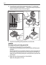
CAUTION:
If any of the wires are incorrectly fitted, the scanner will not
function correctly.
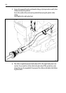
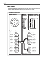
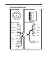
7. Fit the 8-way plug (supplied in the kit of parts) to the cable as shown in the fol-
lowing diagram. The terminal clamps are operated using a screwdriver as
shown.
Connect the plug to the signal connector as shown. When correctly fitted the
white wire (co-axial) will be at the outer edge of the unit.
500 mm ± 10 mm
500 mm ± 10 mm
35 mm
30 mm
15 mm
Black power wires
Data wires
(6 off)
Coaxial
signal
Coaxial
screen
Red power wires
25 mm
10 mm
See Note B
See Note A
Exposed braid
Exposed braid
Exposed braid
5-6 mm strip length
5-6 mm
strip length
5mm maximum
25 mm
35 mm
25 mm
35 mm
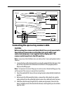
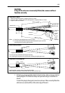
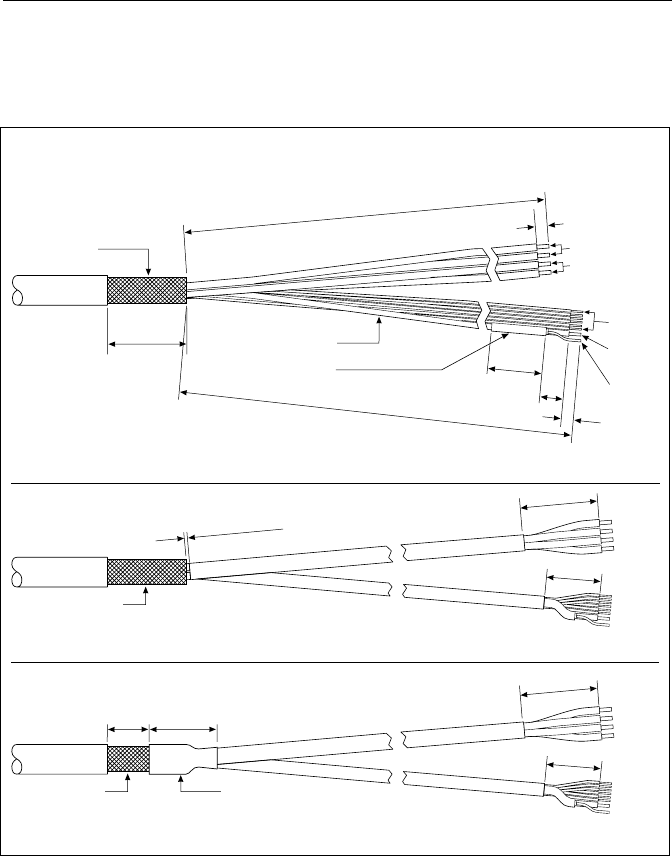
1. Preparation of Wires
2. Heat Shrinking of Wires
3. Preparation of Earthing Braid
Apply heatshrink ensuring at least 15 mm of braid is visible.
When clamped in position the braid should make full contact with the P-clip.
Heatshrink
Form the wires into two bundles with heat-shrink tubing
(one containing the four power wires and the other containing the eight signal wires).
Notes A. Aluminium screen/polyester tape screen to remain.
B. Heat shrink sleeving fitted to keep the aluminium/polyester tape screen from
unwinding from the coaxial signal insulation.
D4579-3
1. Remove the protective sleeve to a length of 535 mm ± 10 mm.
2. Using wire cutters, carefully remove the earthing braid to a length of 500 mm ± 10 mm.
3. Prepare co-axial wire as shown.