


clxxxviii
2.3 Selecting the scanner unit site
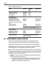
This section provides information that affects the possible locations of the
scanner, and its position relative to the display unit and to the power supply.
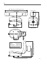
The dimensions of the each scanner unit are shown in the following diagrams.
Selecting the best location for the scanner unit requires careful consideration of
the following points, to ensure reliable and trouble free operation:
Note:
In order to minimize potential interference to other systems on board ship (EMC), it
is advisable to mount the scanner on a part of the boat that is insulated from the ship’s bat-
tery negative. If you cannot do this, and encounter problems, you can fit insulating bushes
between the scanner and its mounting bracket.
• Height: The scanner unit should normally be mounted as high as practical
above the waterline, for three reasons:
• For safety reasons the scanner should be out of range of personnel, pref-
erably above head height. This avoids mechanical danger and electro-
magnetic contact, particularly with the eyes.
Table 2-1: Open array scanners
Item Part No. Supplied
with:
Option for:
4 kW Scanner Pedestal
10 kW Scanner Pedestal
48" Open Array
72" Open Array
M92654-S
M92655-S
M92693
M92743
5S, 7S
9S, 11S
5S, 9S
7S, 11S
-
-
-
-
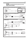
Pathfinder Cables
Inter-unit cable 15 m heavy
Inter-unit cable 25 m heavy
Cable kit: 5 m +10 m extension
(To fit open array scanner on a radar
arch)
Extension cable 5m
Extension cable 10m
M92728
M92705
E55017
M92699
M92700
-
-
-
-
-
5S,7S, 9S, 11S
5S, 7S, 9S, 11S
5S, 7S, 9S,11S
5S, 7S, 9S, 11S
5S, 7S, 9S, 11S
Note: 9S and 11S scanners require 24/32V
C-Series Cables
Split pedestal cable 25m
Split pedestal cable 15m
Pedestal adaptor cable
E05017
E05018
E05019
-
-
-
5S, 7S, 9S, 11S
5S, 7S, 9S, 11S
5S, 7S, 9S, 11S
Software Upgrade Kit Please contact your authorized dealer or
distributor for details