


ccviii
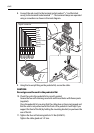
Securing the pedestal to the mounting platform
1. Using the paper template supplied with the scanner mounting kit, mark the
flat mounting surface with the holes and drill as indicated on the template.
Refer to
Section 1.2
when selecting the scanner unit site.
2. Stick the four self-adhesive bitumen washers over the mounting holes.
3. Ensure the lifting eyes are securely fitted to the top of the pedestal, and the
yellow protective cap is in place.
CAUTION:
To prevent damage to the internal mounting bar, ensure the stud
penetration is no more than 32 mm into the pedestal base. We
recommend you mark each stud with tape, 32 mm from one end, to
act as a gauge.
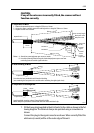
4. Grease the studs with Denso paste (supplied). Using two nuts locked together
on the stud, screw each stud into the pedestal to a maximum of 32 mm, or
until they bottom out. Remove these two nuts.
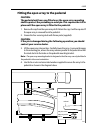
Note:
If the studding supplied is not long enough, use M10 stainless steel, grade A4-70
studding of a suitable length. Refer to the following illustration for details.
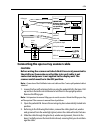
5. Using suitable lifting equipment, raise the pedestal over the mounting sur-
face. Carefully lower into position, taking care that the studs pass through the
holes without damaging the threads. Ensure that the cable inlet is pointing
aft.
WARNING:
Support the pedestal unit until it has been secured to the
mounting platform. It is important that all four sets of nuts and
washers are used to secure the pedestal to the mounting
platform.
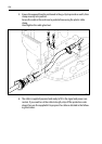
6. Referring to the following illustration, use the four nuts and associated wash-
ers supplied to secure the pedestal. Tighten the nuts to 30 Nm (22.1 lb ft.);
ensure the scanner is tightly fitted.
Grease the nuts with Denso paste (supplied).
If required, cut-off any excess stud.