


ccii
CAUTION:
This radar is not intended for use on “positive” ground vessels.
The power cable Earth screen connections must be connected to
the ship’s ground.
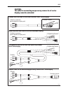
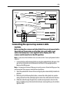
Grounding the radar system
It is important that an effective RF ground is connected to the radar system.
You must ground the radar by connecting the drain wire (screen) of the power
cable to the nearest ground point of the ship’s RF ground system. Refer to your
display unit
Owner’s Handbook
for details.
If you need to extend the wire, the extension wire should be an 8 mm braid or
AWG 10 (6.0 mm
2
) multi-stranded cable.
If your vessel does not have an RF system, connect the drain wire to the negative
battery terminal.
Note:
Use only this ground connection.
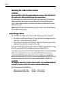
Power Connections
The power connection to the radar should be made at either the output of the
battery isolator switch, or at a DC power distribution panel. Raymarine
recommends that power is fed directly to the radar via its own dedicated cable
system and MUST be protected by a thermal circuit breaker or fuse, fitted close to
the power connection. Refer to the table below for isolator switch, circuit breaker
or fuse value ratings. Check all terminal connections are clean.
CAUTION:
If you do not have a thermal circuit breaker or fuse in your power
circuit, e.g. fitted to the DC distribution panel, you MUST fit an in-
line breaker or fuse to the positive (red) lead of the power cable.
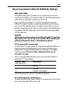
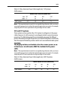
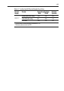
Table 2-7: Isolator Switch/Thermal Breaker/Fuse Value
Vessels
Supply
Device Open Array Systems
4 kW 10 kW
Radome
Systems
12 V*
Isolator Switch min. rating 30 A n/a 20A
Thermal Breaker rating 15 A n/a 10A
Fuse value 20 A n/a 15 A