


cxcvi
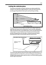
Running the cable to the scanner
CAUTION:
Do not pull the cable through bulkheads using a cord attached to
the connector. This could damage the connections.
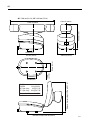
The cable entrance is at the rear of the scanner unit. If the unit is mounted on a
hollow mast the cable may be run inside the mast and then fed through the
radar’s cable entrance. Make sure that the cable does not chafe where it enters
and exits the mast.
Note:
Route the cable from the display up to the scanner, since this will require
the smallest clearance hole.
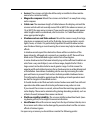
Rejoining cables
You should avoid cutting and re-joining cables. If this is necessary you must:
• Fit a ferrite on each side of the join. The specific ferrite to use depends on the
cable type - contact Raymarine for details.
• Take care not to damage any of the wires. Make sure that all the wires and, in
particular, the screen are reconnected correctly.
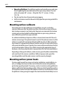
If you are mounting the scanner on the mast of a sailboat, and will need to unstep
the mast, you should install a suitable junction box inside the boat.
On an open array scanner, the junction box should provide a 13-way terminal strip
with a 20 A rating for power cores. It is essential that all 4 power cores are
connected and that the connection is of very low resistance as considerable
power passes through this connection. Also, you should keep the length of the un-
screened coaxial cores to less than 30 mm to maintain EMC conformance.
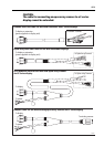
CAUTION:
The display connector on the scanner cable is a moulded plug that
cannot be replaced. DO NOT remove this moulded plug.
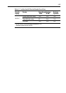
The minimum bends permitted are:
Minimum bend, light cable 60 mm (~2.5 in) radius
Minimum bend, heavy cable 82 mm (~3.75 in) radius