


ccxiv
3.2 System Connections
CAUTION:
The display connector on the scanner cable is a moulded plug that
cannot be replaced. DO NOT remove this moulded plug.
Do not use an open array scanner with an SL70, SL70 PLUS or
SL70RC PLUS 7" LCD display unit. Failure to observe this may
result in permanent damage to the display unit.
10 kW open array scanners cannot be directly connected to 12 V
systems.
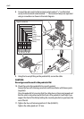
Scanner Connections
The inter-unit or split pedestal cable is connected to the scanner as previously
described in
Connecting the radome scanner inter-unit cable
on
page 24
or
Connecting the open array scanner cable
on
page ccix
.
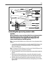
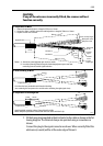
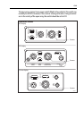
Display Connections
The inter-unit or split pedestal cable is connected to the display unit with the
moulded plug; the following illustration identifies the scanner connector on the
various display connector panels.
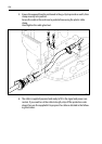
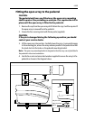
If you are using an inter-unit extension cable, connect this to the display unit, and
connect the supplied cable to the extension cable.
You cannot extend the split pedestal cable or pedestal adaptor cable.
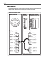
Power Connections
DC power requirements are described in
Section 1.5, Power Requirements
.
Power for an open array scanner connected to a Pathfinder display and for any
radome scanner is supplied via the display unit - refer to your
Display Unit Owner’s
Handbook
for connection details.
An open array scanner is connected to a C-Series display via the split pedestal or
adapator cable.You must use the pedestal adapter cable to connect a C-Series
display to an existing open array scanner unit with a standard inter-unit cable;
connect the adaptor between the inter-unit cable and the display.
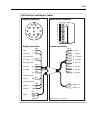
The following connections to the boat’s DC power are required:
Red Battery +ve (12/24 V)
Black Battery -ve (0 v)
Green Ground