


Trekker - Squab
4x 10w
D
1,2w
5A
5
on
off
6
3
1
4
12V 4Ah
21
20
19
16
2
15
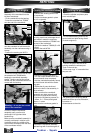
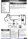
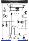
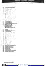
2 - Ignition switch
15 - Battery
16 - 5A Fuse
19 - Turn signal relay
20 - Indicator control
21 - Indicator bulbs
D - Indicator telltale
18
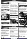
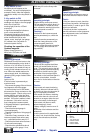
ELECTRIC EQUIPMENT
1. Key switch to OFF
No display should appear on the
multimeter. If a value is displayed (for
example 0.5mA), either the regulator
(connection wires) or the key switch is
faulty.
2. Key switch to ON
A slight discharge can be explained by
sending a volt supply to the fuel gauge
and to the oil low level
warning light (0.9mA to 1OOmA
maximum).
A significant dischar@e indicates a
more or less earthed circuit.
Disconnect the various circuits until
the discharge disappears and locate
either the defective unit or wire
(starter, motor, stop light, fuel gauge,
oil, indicator, horn, key switch or
instrument panel circuits).
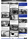
Checking the capacities of the
flywheel magneto.
Battery charge (current = )
White wire = 0.7 ohm and earth.
Operating principle
A direct current supplies the blinker
control unit located under the front
cover. This current is sent to the left-
hand grip handle to be distributed by
the switch to the left-hand or right-
hand bulbs of the turnsignal lights.
The telltale on the instrument panel is
common to both sides. Its earth
return line is via the bulbs on the side
not used.
Checks :
If the central unit starts functioning
erratically, either an indicator bulb is
not working or the main connecter (9-
way) is not properly connected.
If the central unit makes a crackling
sound, either there is a short circuit
between an orange or blue wire and
earth or the battery is discharged.
If the central unit does not work,
before changing it, check:
- Battery voltage (it must be over 10
volts).
the 4 bulbs of the indicators and the
telltale bulb.
- that the central unit is supplied with
12 volts (if not, check the fuse, the key
switch, the connections, the black
wire).
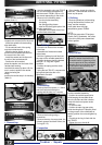
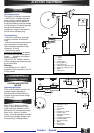
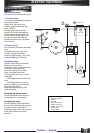
HORN
Operating principle
Supplied with a continuons current, a
horn and a switch are fitted in series.
Check :
- If the horn does not work, check the
circuit (fuse, key switch, left-hand grip
handie switch), in order to get 12 volts
at the horn terminals.
- Check that the horn is planned for
use with continuons current (presence
of an adjustment screw, here hidden
by a plug). Horn test
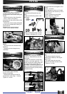
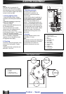
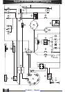
FUEL GAUGE
Operating principle
Resistance from the fuel meter to the
tank varies depending on the level of
fuel from 10 to 100 ohms. On the ins-
trument panel, the needle will vary ac-
cording to this resistance from min. to
max. When the needle reaches the
reserve supply level, this indicates a
remaining riding range of about 25km.
Checks :
ignition to ON
If the fuel meter is permanently at
maximum level:
- Disconnect the gauge if the minimum
level appears, check the gauge.
- If the maximum level is still shown,
disconnect the 5-way connector on the
instrument panel. Check, using a mul-
timeter (MX40), set in the ohm posi-
tion, that the yellow / white wire is not
earthed. If this wire is earthed, check
the harness. If this wire is not ear-
thed, change the instrument panel.
If the gauge indicator is permanently
at minimum level:
- Check that the tank gauge is
connected properly
- Check the capacities of this gauge (5
to 100 Ù)
- Check the 5-way connector on the
instrument panel: black wire to way
no.1, yellow/white wire to way N° 4.
- Check that the black wire receives a
12 volt continuons supply.
- Check that the yellow/white wire is
continuons up to the gauge. If not,
OIL GAUGE
Operating principle
Supplied with a continuons current.
The float acts like a switch; when it is
in a low position, it closes the circuit
which causes the warning light on the
instrument panel to come on.
Checking :
If the bulb on the instrument panel
remains permanently on, check the
float.
If the bulb remains permanently on,
check the 4-way connector on the
instrument panel (terminal 4,
the blue / white wire must not receive
a 12 volt supply while the float is in
high position).
check way N°1 on the 9-way main
connector.
INDICATORS