


Trekker - Squab
Bleed screw
FITTING
14
Mark
PARTIE CYCLE
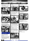
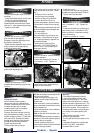
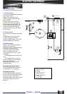
Fitting the cooling systern
- Position and fasten the fan onto the
rotor (4 screws L = 1 8). Tighten to 1
m.dan.
- Position and fasten the cylinder case
and cooling cover (4 screws M = 25).
Make sure that it is fastened correctly
around the sensor.
- Tighten to a torque of 1 m.dan.
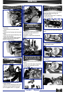
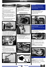
Fitting of the oil pump
- Position both square nuts (Q) in their
housings.
- Place the flexible washer on the seat.
- Position the pump fitted with its
«0»ring, position the sheath stop
fastening hook and fasten the cluster
with two n».4 hex head socket screws.
- tighten to 0.8m.daN.
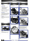
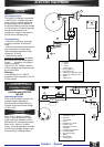
Adjustment of the oil purnp
1) Check the free play in the throttle
grip (2 to 5mm) and adjust if
necessary using the adjusting screw.
2) Open the throttle fully.
-Check that the alignment mark on the
pump control lever is opposite the
mark on the pump body.
- Adjust if necessary by turning the
pump cable abjusting nuts.
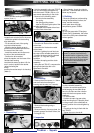
Checking the lubrication
circuit
- Supply the carburettor from a
separate tank containing 2-stroke fuel
mixture.
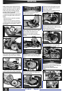
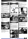
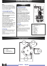
Fitting the flywheel
- Position the stator / sensor assembly
on the crankcase.
- Fasten with 4 screws (2 screws L =
16, 2 screws L = 20). Tighten to 1
m.dan.
- Make sure that the woodruff key is
indeed on the crankshaft.
- Disconnect the oil input hose on the
pump and check the oil flow. Check
also :
. that there is oil in the tank,
. that the hose is not trapped,
. that the oil filter is not blocked,
. that the tank filler hole is not
blocked (atmospheric pressure hole).
- Reconnect the hose onto the pump
body.
- Open the pump bleeding screw until
ail the air bubbles have escaped and
then close again.
- Turn the engine on.
Disconnect the oil input hose on the
carburettor. Check that the oil drips
out. Dripping frequency depends on
the engine’s speed
- Reconnect the hose onto the
carburettor. OIL PUMP FLOW: 24
cm3 ± 1.7cm3 hour at 3800 rpm.
Wide open throttle.
- Position the rotor.
- Keep the rotor in place using the ad-
justable pin type face wrench 752237.
- Tighten the nut at 4m.daN.
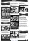
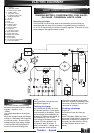
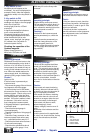
DISK BRAKE
Filling the circuit :
At the receiver (brake calliper),
remove the cap of the bleed screw.
Connect a flexible hose to this screw,
the other end put into an empty
container (fuel hose for example).
Loosen this bleed screw.
Remove the cover and seal, with the
tank positioned horizontally, f rom the
emitter (master cylinder). Fill the tank
with brake fluid. Activate the brake
handle gently until the liquid comes
through to the bleeding container.
Tighten the bleed screw.
Fill the emitter tank to the top.
Activate the brake lever several times
with the cover refitted.
Loosen the bleed screw again. Air
bubbles should escape through the
flexible hose.
When there are no more air bubbles,
tighten the bleed screw with the brake
lever constantly on.
Repeat the operation until no bubbles
appear in the liquid.
Note: At the end of the opération, top
up the level.
- It is sometimes necessary to tap the
elements of the brake system lightly in
order for the air to escape.
- Certain callipers need to be
dismounted in order to place the bleed
screw in the high position.
Warning :
- The brake fluid attracts humidity.
ln certain conditions humidity may
impair braking efficiency. You must
always use brake fluid from a recently
opened container (tightness cap). The
liquid recovered in the bleed container
must not be reused. Do not open the
container when there is a high degree
of hi-imidity in the atmosphère (rain,
fog .... ).
- Brake fluid is corrosive. Avoid
spillage on painted parts.
- Do not spill fluid onto the pads or the
disks.
- Use brake fluid which complies with
the DOT 3 or DOT 4 standards.
(Lockeed D55 for exam
CYCLE PART