


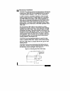
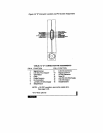
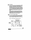
“D”
connector.
“D”
connector are shown in Figure 2-2, and the pin assign-
ments are given in Table 2-2. Operating power input and
output signals are supplied via the
theFMA-1900 enclosure. The pin numbers of this
“D”
connector located on
the side of
15-pin
mA
output or input section.
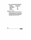
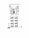
FMA-1900 is provided with a
PSIG
Inlet and Ambient Outlet)
Flow Ranges
Relative to N2
O-10 to O-500 SCCM
O-500 to O-l 000 SCCM
O-2 to O-5 SLM
O-10 SLM
O-l 5 SLM
O-30 to O-50
SLM
Valve Orifice Diameter
(Typical-in inches)
0.02
0.03
0.05
0.05
0.065
0.083
2.6 Electrical Connections
CAUTION: The FMA-1900 is not a loop powered device! Do
NOT apply power to the 4-20
TABLE 2-1 TYPICAL MINIMUM RESTRICTION DIAMETERS
(Under Standard
AP
Conditions of 39