


[
15 to 250 SLM].
A regulated power supply is required. Ripple content
should not exceed 50mV peak to peak.
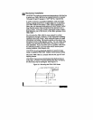
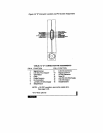
Refer to the component location diagram (Figure 3-2) for
the location of Jumper J3.
250mA,
Jumper J3 open (shorting block
removed)
@
160mA,
Jumper J3 closed (shorting block
installed) [If less than 15 SLM].
24 VDC
@
%).
Overrange conditions are indicated by the display and/or
output going to a high level, above the full scale range.
After the over-range condition has been removed, it may
take several minutes for the FMA-1900 to recover and
resume normal operation.
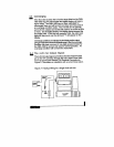
The FMA-1900 has more stringent power supply require-
ments due to the presence of the valve.
Because the valve
is operated in a control loop, power supply variations
cannot be tolerated. This means the power supply must be
a regulated 24 VDC with ripple not to exceed 50mV peak to
peak, and capable of producing at least 250mA (6 watts).
The standard power supply for both the FMA-1900 is 24
VDC. It is possible to operate the FMA-1900 on 15 VDC at
reduced performance levels. There is a direct relationship
between the amount of power the valve requires and the
flow rate. Due to this relationship, 15 VDC powered
controllers are limited to a flow rate of 15 SLM. To achieve
flow rates above
15
SLM, use a 24 VDC power supply.
The minimum power requirements for all FMA-1900
controllers are as follows:
15 VDC
l/2
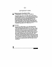
digit LCD display reads directly in
engineering units or optional percent of full scale. The full
scale range and gas are shown on the instrument data tag.
The decimal point for the flow rate is set at the factory and
will show automatically (e.g., “5.54” SLM or “76.4”
6
7.
8.
Integral Display: The 3