


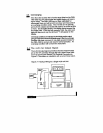

6.%?UNCx.t3LG
2.75
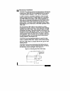
BSCREWx.15DP2
PLBSELFTAF$‘INGTYPE
t
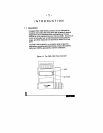
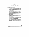
2- 1 Mounting the FMA- 7900 Series
.15”(4mm),
the flow body may be damaged. See Figure 2-1.
Figure
.15”(4mm).
If screws extendfurtherthan
self-
tapping screws.
CAUTION: These screws should extend into the flow body no
furtherthan
“B”
#6,
type
(5O”C),
respectively.
In order to ensure a successful installation, inlet and outlet
tubing or piping should be in a clean state prior to plumbing
your FMA-1900 to the system. FMA-1900 is applicable to
clean gas only because patticulates and other foreign matter
may clog the sensor tube and laminar flow element over a
period of time. If the gas contains particulate matter install a
high-efficiency, 50 to 100 micron, in-line filter upstream of the
FMA-1900.
Do not locate the FMA-1900 in areas subject to sudden
temperature changes, moisture, or near equipment radiating
significant amounts of heat. Allow adequate space for cable
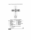
connectors and wiring. Be sure the arrow on the side of the
transducer points in the direction of flow. You can obtain best
results if you operate the FMA-1900 in the plane in which it
was calibrated. If you mount the unit in a position other than
its calibrated position, you may have mild to severe perfor-
mance problems. (See Section 3.6.)
CAUTION: Do not use liquid leak detectors to search for leaks
inside or outside the FMA-1900.Instead, monitor pressure decay
Mount the FMA-1900 to a chassis with two
kg/cm*
gauge) or 122°F
2.4
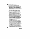
Mechanical Installation
CAUTION: The maximum pressure and temperature in the flow line
in which your FMA-1900 is to be installed should not exceed
150 psig (10