


mA
is for zero flow.
mA
is for one-half of full scale; and 4.00
mA
is the output signal for the full scale; 12.00
mA
output
signal, 20.00
linearty
proportional to the gas
mass flow rate. The full scale range and the gas for which
the unit was calibrated are shown on the FMA-1900 data
tag. Section
2.6,
ELECTRICAL CONNECTIONS, describes
the electrical output signal hookup. For example, if you are
monitoring the O-5 VDC output signal, 5.00 VDC is the
output signal for the full scale listed on the FMA-1900 data
tag; 2.50 VDC is for one-half of full scale; and 0.00 VDC is
for zero flow.
If you are monitoring the 4-20
mA
output signals. The effective
control range of the unit is 10% to 100% of the calibrated
flow range. The output is
mA
output or input section.
4.
After the warm-up period, your FMA-1900 will begin
monitoring the gas mass flow rate.
5.
Output Signals: The FMA-1900 has either O-5 VDC (O-l 0
VDC optional) or 4-20
4mA,
depending on output configu-
ration). Allow at least 15 minutes for complete warmup.
CAUTION:
The FMA-1900 is not a loop powered device!
Do NOT apply power to the 4-20
“D”
connec-
tor on the side of your FMA-1900, then plug the power
supply into line power. If you are providing your own
power source, refer to Section 2.3, paragraph 8, for
specific power supply requirements and jumper settings.
3.Upon application of power, the output signal will be at a high
level for the first 10 to 20 seconds, after which (assuming zero
flow) it will drop to 0 VDC (or
15-pin
kg/cm*
gauge) or 150°F (66°C). Maximum
operating pressure differential is 50 psig.
2.
Apply power to your FMA-1900. If you are using the
Omega power supply, connect it to the
l/4-inch pipe, use a good
quality paste pipe thread sealant. First tighten the fittings
by hand, then tighten no more than one and a half turns to
avoid cracked fittings or creating a calibration shift.
The line pressure and temperature should not exceed 150
psig (10
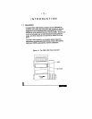
2.3
Before Beginning the Installation
Read the following notes in their entirety before beginning
actual installation of your FMA-1900 flow controller.
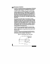
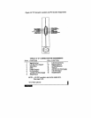
1.
Using the flow direction arrow on the FMA-1900 to prop-
erly orient the controller, install the FMA-1900 into the gas
flow line. If you are utilizing