


35
TRACKER 5100/5100i/5500/5500i Installation and Operation Manual
NAVMAN
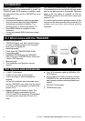
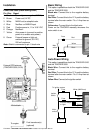
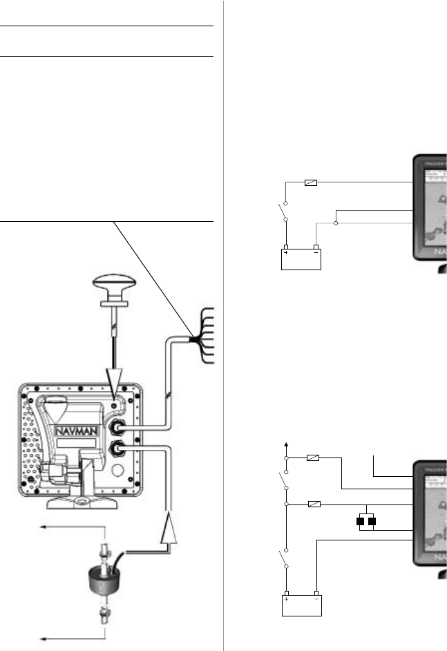
External GPS antenna
(TRACKER 5500, 5100)
Fuel transducer(s)
(optional)
Installation
To fuel tank
To engine
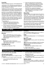
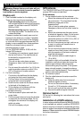
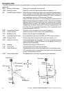
Auto Power Wiring
This option is possible on both the TRACKER 5100
and the TRACKER 5500.
Black Wire: Connect this to the negative battery
terminal.
Red Wire: Connect this to the 12 V positive battery
terminal after the main switch. Fit a 1 Amp fuse as
shown.
Yellow Wire: Connect to the ignition switch
Fuse
Fuse
White (NMEA out)
Green
External Beeper
or Light
Red
Yellow
Black
Main
switch
12 V DC
Ignition
switch
To ignition system
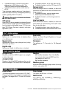
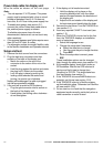
Fuse
Red
Yellow
Black
Main
switch
12 V DC
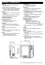
Basic Wiring
This option is possible on both the TRACKER 5100
and the TRACKER 5500.
Black wire: Connect this to the negative battery
terminal.
Red Wire: Connect this to the 12 V positive battery
terminal after the main switch. Fit a 1 Amp fuse as
shown.
Yellow wire: Connect this to the black wire.
Power on the TRACKER manually whenever the
main switch is on.
Power/data cable (black locking collar)
Pin Wire Signal
1 Black Ground (power negative, NMEA)
2 Brown Power out, 9 V DC
3 White NMEA out, to autopilot/radar
4 Blue NavBus - or NMEA2 input
5 Red Positive power in, 11 to 16.6 V DC
6 Orange NavBus +
7 Yellow Auto power in (connect to positive
power in to enable auto power)
8 Green External beeper or light out,
switched to ground, 30 V DC,
200 mA maximum
Note: Shield is connected to pin 1, black wire