


33
TRACKER 5100/5100i/5500/5500i Installation and Operation Manual
NAVMAN
15-3 Installation
Warning: Ensure that any cut holes will not
weaken the boat. If in doubt, consult a qualified
boat builder or marine engineer.
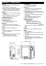
Display unit
1 Find a suitable location for the display unit:
There are two mounting arrangements:
Flush mounting requires a solid panel
with access behind for wiring and mounting
screws. Do not flush mount a TRACKER
5500i or 5100i.
Bracket mounting requires a panel for
mounting the bracket. The bracket can be
rotated and tilted.
Choose a location that is easily seen and not
exposed to the direct sun or water. If possible,
mount the display unit in front of the navigator
or to the left of the navigator because the LCD
display is more readable from these positions.
Keep the unit away from any source of
electrical signals or noise.
For the TRACKER 5500i or 5100i, with the
internal GPS antenna:
The display unit must have a good view of
the sky and horizon. The view should not
be blocked by large parts of the
superstructure.
The unit can be under glass, perspex,
fibreglass or fabric, but not under metal or
wood.
Do not mount the unit within 3 m (10 ft) of a
radio transmitter antenna or within 0.5 m
(20") of the plane of a radar antenna.
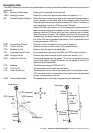
2 For flush mounting:
i Cut a hole in the bulkhead for the display
unit using the flush mount template.
ii Drill four holes for the mounting studs
using the flush mount template.
iii Screw the four studs into the brass inserts
in the back of the display unit.
iv Sit the display unit in place and fit the
washers and nuts to the studs.
For bracket mounting:
i Hold the bracket in place and mark the
screw holes.
ii Drill the screw holes and screw the bracket
in place with the screws provided. Do not
overtighten the screws or the display unit
might not rotate.
Do not fit the display unit yet.
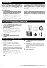
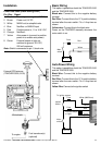
GPS antenna
The TRACKER 5500 and 5100 require the supplied
external GPS antenna to be fitted.
Fit the antenna
1 Find a suitable location for the antenna:
Mount the antenna with a good view of the
sky and horizon. The view should not be
blocked by large parts of the
superstructure.
The unit can be under glass, perspex,
fibreglass or fabric, but not under metal or
wood.
Mount the antenna away from any source
of electrical signals or noise. Do not mount
the antenna within 3 m (10 ft) of a radio
transmitter antenna or within 0.5 m (20") of
the plane of a radar antenna.
Do not fit the antenna too high, such as up
a mast, or rocking will cause errors in
speed and bearing.
Do not mount the antenna where it can be
used as a hand hold, where it will interfere
with the operation of the boat or where it
might be submerged.
The maximum antenna cable length is
15 m (49 ft).
If a location might not be suitable, follow the
installation instructions below but mount the
antenna and antenna cable temporarily,
without drilling any fixing holes. If the system
does not work properly, change the antenna
location until it works properly. Then install the
antenna and cable permanently.
2 Fit antenna in place.
3 Run the cable between the antenna and the
display unit:
Keep the cable away from sources of
electrical signals or noise.
Do not cut the antenna cable; if necessary,
fit one 5 m (16 ft) extension cable.
Do not crush or pinch the antenna cable.
Secure the cable at regular intervals.
Optional fuel kit
Fit the fuel kit following the instructions that come
with the kit.
Installation of a DGPS antenna
In areas where satellite differential(WAAS/EGNOS)
is not available an optional combined GPS/DGPS
antenna may be connected for enhanced accuracy
when in range of conventional land based differential
beacons. Please contact the nearest NAVMAN dealer
for further information.