


Wiring (continued)
9
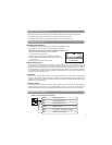
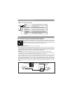
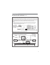
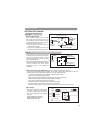
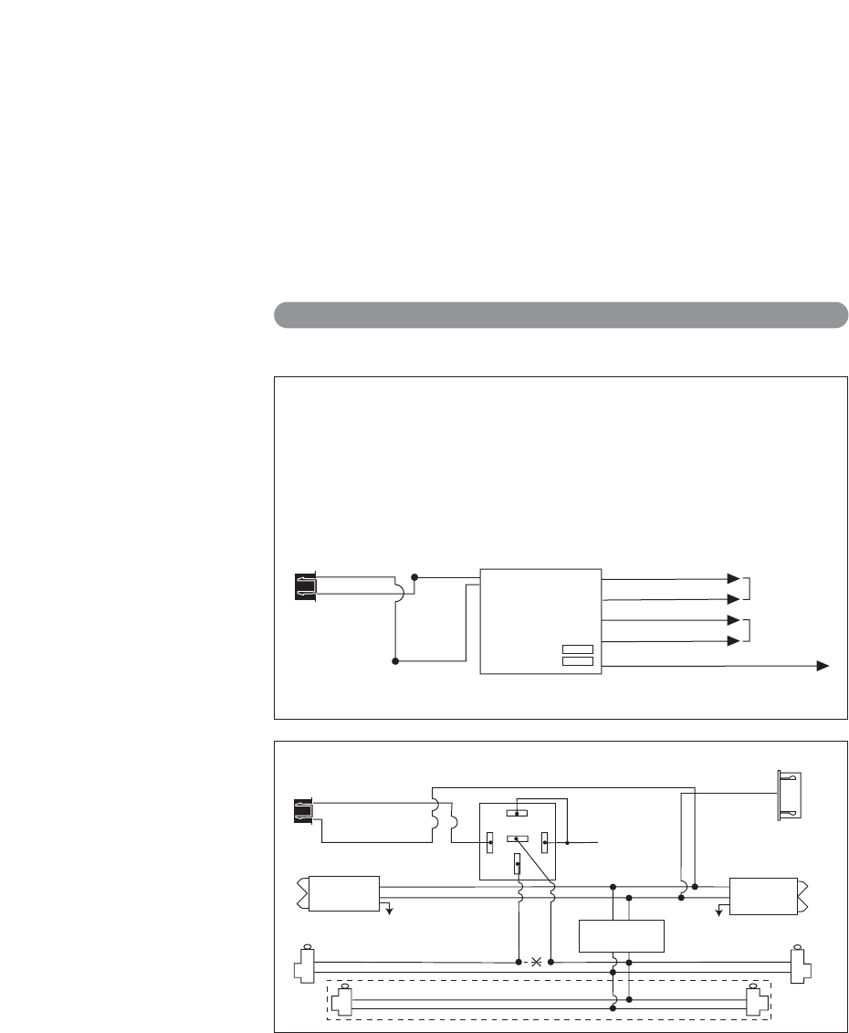
Unlock Driver's Door First for 3-Wire Negative Door Lock Systems
87
87A
85
86
30
Unlock Wire
Passenger's Door
Lock
Unlock
To +12V or Ground
To +12V or Ground
Driver's Door
Rear Doors
Passenger's
Door Switch
Door Lock Relay
Control Module
Lock
Unlock
+12V
ALA984H
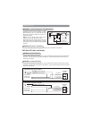
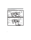
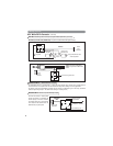
Relay
Driver's Door
Switch
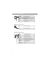
Cut
Blue Wire
Green Wire
White Wire
White 6-Pin Mini
Connector
HC3: Black 3-Pin Door Lock Harness
(continued)
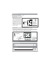
White Wire Lock
To Power
Lock Switch
To Power
Lock Motors
Brown Wire Unlock
Green Wire Lock
Blue Wire Unlock
Violet Wire To +12 Volts Constant
Lock Fuse 1
Unlock Fuse 2
ALA-DL1
Red Wire
Black Wire
Black 3-Pin
Mini Connector
Green Wire
Blue Wire
Note: Orange wire from ALA-DL1 must be connected to +12V.
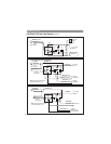
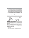
One Wire Multiplexing Door Locking Systems
Some vehicle’s (Chrysler, Mazda and Ford Probe and others) use one wire to lock and unlock the doors.
Example: When the door lock controller sees a signal thru a resistor it will unlock. If a signal is received
without a resistor the doors will lock. Some use 2 resistors. One for lock and one for unlock. We have
developed patented plug-in fuse resistors for this application. Simply remove the fuse from our door lock
module and replace with correct resistor value fuses that matches the vehicles door lock switch.
Wiring:
1. Connect both the green (lock) and the blue (unlock) wires to the vehicles one wire lock/unlock wire.
2. Connect our violet polarity input wire to +12v or to ground. To match vehicles door lock polarity.
3. The white and the brown wires will not be used.