


7
Wiring (continued)
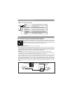
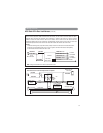
By default, the Brown wire is the positive (+) output
connection for the siren. Current capacity is 2 amps.
Make connection to the (+) red wire from the siren.
Connect the (-) black wire coming from the siren to a
good chassis ground.
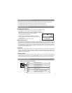
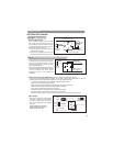
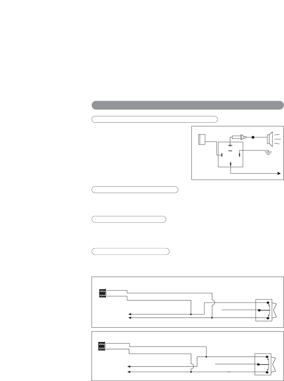
Option: (+) Horn Output (See “Alarm Feature
Programming” to change the function to horn)
Connect this wire to the existing vehicle’s horn relay
trigger. Some vehicle horn systems may be (-) trigger
and a relay will need to be added for proper operation
as shown.
The “Red” wire supplies power to the system. Connect this wire to a constant +12 volt source.
87
87a
86
85
30
Brown
Wire
To Ground
To Horn
+12V or Ground
Depending on
System Requirements
Fuse
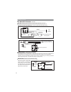
White
5-Pin
Connector
Brown Wire: (+) Programmable Output - Siren Default Setting
Red Wire: System Power, +12V Constant
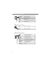
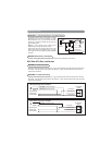
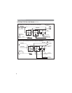
HC3: Black 3-Pin Door Lock Harness
If the door lock control system on the vehicle is (-) type, connect the Blue wire to the unlock wire from the door
lock switch . If the door lock control system on the vehicle is (+) type, connect the Blue wire to the lock wire
from the door lock switch.
If the door lock control system on the vehicle is (-) type, connect the Green wire to the lock wire from the door
lock switch . If the door lock control system on the vehicle is (+) type, connect the Green wire to the unlock wire
from the door lock switch.
Blue Wire: (+/-) Door Lock Control
Green Wire: (+/-) Door Lock Control
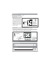
3 Wire Ground Trigger Door Lock System
(
-
) Lock Out
Ground Input
(
-
) Unlock Out
To Door Lock
Control Relays
Lock Control
Switch
Blue Wire: Connect to Unlock
Green Wire: Connect to Lock
Black 3-Pin
Mini Connector
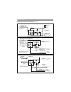
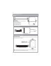
3 Wire Positive Trigger Door Lock System
(+) Lock Out
+12 Volts Input
(+) Unlock Out
To Door Lock
Control Relays
Blue Wire: Connect to Lock
Green Wire: Connect to Unlock
Lock Control
Switch
Black 3-Pin
Mini Connector