


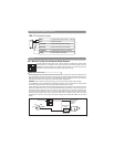
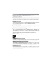
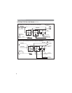
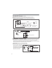
Windshield Receiver/Antenna
• The combination windshield receiver/antenna mounts on the windshield (inside).
• We suggest you mount it on the lower left-hand side of the windshield.
Warning! Do not mount in such a manner that it obstructs the driver’s view.
• The receiver/antenna whip can be vertical or horizontal.
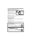
1. Remove the protective tape backing.
2. Carefully align the receiver/antenna and apply to windshield.
3. Route the black connecting cable behind the trim and connect to
receiver/antenna.
4. Connect the other end to the control module.
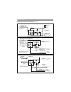
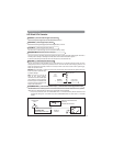
Dual-Zone Shock Sensor
Select a mounting location within the passenger's compartment or trunk. Do not mount in the engine
compartment or in any location where it will get wet, greasy or will be subject to heat, direct or indirect. To
achieve the best overall level of protection, select a mounting location that is centrally located in the vehicle. It
will be necessary for the shock sensor to be somewhat accessible to make the correct sensitivity adjustment.
The mounting surface should be as flat as possible for best sensitivity. The sensor can be mounted in any
position as long as it is solidly mounted.
Valet Switch
Select a mounting location for the switch that is easily accessible to the driver of the vehicle. The switch does
not have to be concealed, however, concealing the switch is always recommended, as this provides an even
higher level of security to the vehicle. Mount the valet switch in a hidden but accessible location. Route the valet
switch wires to the control module.
LED Status Indicator
The LED indicator status should be mounted in a highly visible area. Leave at least 6mm of space behind the
mounting location for LED housing. Once a suitable location is chosen, drill a 1/4" hole. Run the LED wires
through the hole then press the 2-pin LED housing into the place. Route the LED wires to the control module.
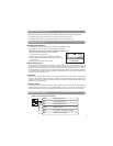
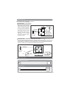
Mount the antenna horizontally
for best reception.
Component Placement
3
• All wires that operate at currents higher than 10A should be soldered to insure a long lasting connection.
• Install wiring neatly under carpets or behind trim to prevent possible damage to wires.
• For dealer technical assistance, please call (800) 638-3600 or visit www.magnadyne.com
Installer Warnings (continued)
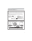
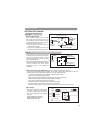
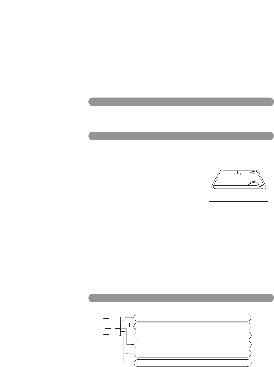
Harness Quick Reference
HC1 8-Pin Remote Start Harness
Violet Remote Starter Output
Red +12VDC Battery Input #1
Yellow +Ignition 1 Output
Red +12VDC Battery Input #1
Brown +ACC / Heater - Air Conditioner Output
Pink +Ignition 2 / ACC 2 Output