


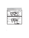
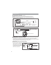

HC1: White 6-Pin High Current Remote Starter Harness (continued)
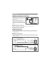
Remove the two 20A fuses prior to connecting these wires and do not replace them until the harness has been
plugged into the control module. These wires are the source of current for all the circuits the relay harness will
energize. They must be connected to a high current source. Connection to 12V battery terminal recommended.
Connect the Yellow wire to the ignition 1 wire from the ignition switch. The ignition wire should receive
+12 volts when the ignition key is in the “ON” or “RUN” and “START” or “CRANK” position. When the ignition is
turned “OFF”, the ignition wire should receive “0” voltage. The yellow wire must be connected.
Some vehicles have 2 ignition wires that must be powered. Connect the “Pink” wire to the ignition 2 wire from
the ignition switch. No connection required on vehicles without second ignition.
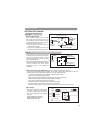
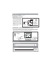
Connect the Brown wire to the accessory wire that powers the climate control system. An accessory wire will
show +12 volts when the ignition switch is turned to the “ACCESSORY” or “ON” and “RUN” positions, it will
show 0 volts when the key is turned to the “OFF” and “START” or “CRANK” position. There will often be more
than one accessory wire in the ignition harness. The correct accessory wire will power the vehicle’s climate
control system. Some vehicles may have separate wires for the blower motor and the air conditioning
compressor. In such cases, it will be necessary to add a relay to power the second accessory wire.
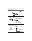
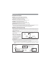
HC2: White 5-Pin Power Harness
The Red/White wire has already been assembled to work with a +12 volt switched parking light system (most
vehicles). For vehicles with ground switched parking light activation cut this wire and connect it to ground.
Connect the White wire to the parking light wire coming from the headlight switch. Do not connect the White
wire to the dashboard lighting dimmer switch (damage to the dimmer will result). The limitation of the White
wire is 10 amp maximum. Do not exceed this limit or damage to the alarm and parking relay will result.
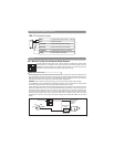
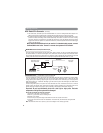
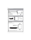
This is main ground connection of the alarm module. Make this connection to a solid section of the vehicle
chassis. Do not connect this wire to any existing ground wires supplied by the factory wire loom, make the
connection to the vehicle’s chassis directly.
6
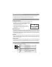
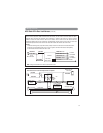
Red Wires (2): +12V Power Input
Yellow Wire: Ignition 1 Output
Pink Wire: Ignition 2 Output
Brown Wire: Accessory Output, Heater/AC Output
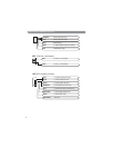
Red/White Stripe: Parking Light Relay Input
White Wire: Parking Light Relay Output, + or - Selectable
Black Wire: System Ground
Wiring (continued)