


12
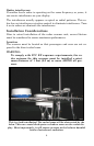
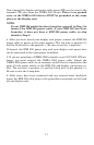
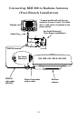
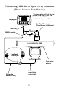
Connecting RIM 200 to Radome Antenna
(Four-Branch Installation)
Display unit
RIM 200
data cable
(RS-422)
LRA 1000, LRA 1500 & LRA 2000
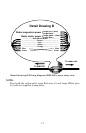
See Detail Drawing C
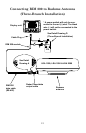
(
Fou
r
-Branch Installation
)
12V
RIM 200 module
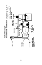
See Detail
Drawing A
Radar Power/data
output cable
Cable Plug
Radome
antenna
*
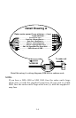
A
power switch will only be con-
nected to the red (+) wire. The black
wire (–) will not be connected to the
power switch.
*
*
*
*