


9
Section 3: RIM 200 Installation
The RIM 200 will replace the power cable that came with your display
unit. Early RIM 200 models have four cables branching out from the
cable plug. The cables include: RIM 200 radar data cable (will be con-
nected to your radar), RIM 200 power cable, display unit power/data
cable and NMEA 2000 network power cable.
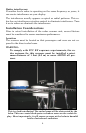
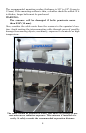
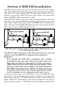
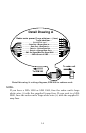
Newer RIM 200 models have three cables branching out from the cable
plug. The cables include: RIM 200 radar data cable (will be connected to
your radar), display unit power cable and NMEA 2000 network power
cable. The three-branch RIM 200 differs from the four-branch model in
that it does not have a RIM 200 power cable.
RIM 200 model with three cable branches (left). RIM 200 model with
four cable branches (right).
You MUST remove the power cable that came with your unit and
replace it with the RIM 200 to complete this installation.
WARNING:
Even though the RIM 200 is replacing your original
power/data cable, you must follow the same rules, cau-
tions and warnings for powering the display unit and a
NMEA 2000 network or LGC-3000 antenna module. These
details are described in the display unit manual and the
LGC-3000 instruction sheet. Failure to follow all power
connection instructions and fusing requirements could
result in damage to your equipment and injury to you.
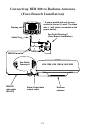
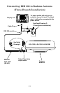
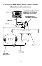
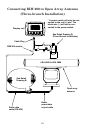
1. Route the radar cable to the RIM 200. Connect the RIM 200 radar
data cable to the radar antenna power/data output cable using heat-
shrink butt connectors. The following pages contain several wiring dia-
grams. Follow the instructions on the wiring diagram for the type of
radar antenna you have — Detail Drawing A for radome models or De-
Fou
r
-branch RIM 200
Three-branch RIM 200