


7
Section 2: Radar Installation
Preparations
Unpack your new radar and check the contents against the packing list.
Do not remove the cover from the unit. There are no connections or ad-
justments inside the unit needed for installation or operation.
The cable must remain attached. For ease of handling, coil the cable
and place it on top of the scanner, then secure it with tape.
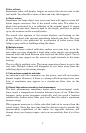
WARNING:
To comply with FCC radio frequency (RF) exposure re-
quirements, the radar antenna for this scanner must be
installed a minimum distance of 1 foot (0.3 m) or more
ABOVE all persons.
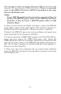
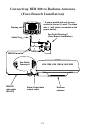
Radar Antenna Installation Procedure:
Prepare the mounting surface by making sure it is clean and flat.
NOTE:
It is a good idea to check the accuracy of the enclosed paper tem-
plate by measuring the actual dimension between the hole loca-
tions. The printing process and moisture absorption can affect accu-
racy of the print.
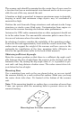
To install radar antenna:
1. Use the template provided and mark the location of the four mount-
ing holes. Align the template squarely with the center line of the vessel,
with the arrow pointing toward the bow.
2. Drill four 1/2" (13 mm) diameter holes through the mounting surface.
3. Check that each bolt (with lock washer and flat washer) protrude
through the mounting surface at least 5/16" (8 mm) but less than 9/16"
(15 mm). If installing a radome model, the bottom of the unit
could be damaged if bolts protrude more than 9/16" (15 mm).
4. Apply marine sealant around each mounting hole.
5. Place the radar scanner unit on the mounting surface. Orient the
scanner with the index mark on the housing facing forward (cable
gland should be facing aft).
6. Install and tighten four M10 x 25U (M10 x 1") mounting bolts. Use
anti-corrosive grease on each bolt to avoid difficulty in removing the
bolts later on.
7. Uncoil the scanner cable.