


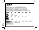
128-7857
6 of 24
6
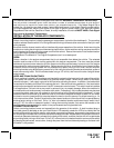
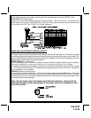
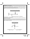
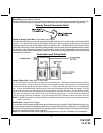
YELLOW WIRE: Starter Output
Careful consideration for the connection of this wire must be made to prevent the vehicle from
starting while in gear. Understanding the difference between a mechanical and an electrical Neu-
tral Start Switch will allow you to properly identify the circuit and select the correct installation
method. In addition you will realize why the connection of the safety wire is required for all
mechanical switch configurations.
Failure to make this connection properly can result in personal injury and property damage. In all installations
it is the responsibility of the installing technician to test the remote start unit and assure that the vehicle
cannot start via RF control in any gear selection other than park or neutral.
In both mechanical and electrical neutral start switch configurations, the connection of the Yellow wire will be
made to the low current start solenoid wire of the ignition switch harness. This wire will have +12 volts when
the ignition switch is turned to the start (crank) position only. This wire will have 0 volts in all other ignition
switch positions.
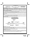
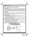
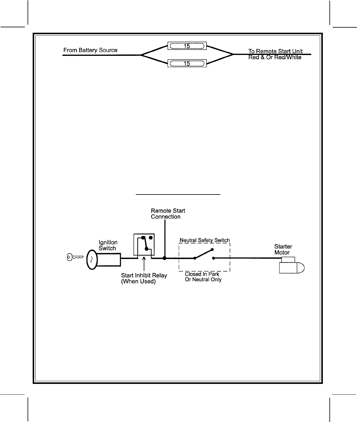
NOTE: This wire must be connected to the vehicle side of the starter cut relay (when used). For the electrical
neutral switch configuration, this connection must be made between the starter inhibit relay, (when used) and
the neutral safety switch as shown in the following diagram.
Failure to connect this wire to the ignition switch side of the neutral safety switch can result in personal injury
and property damage.
SEE NEUTRAL START SAFETY TEST FOR FURTHER DETAILS.
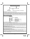
YELLOW START WIRE DETAIL
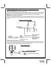
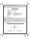
BLUE Wire: Ignition 1 Output
Connect this wire to the ignition 1 wire from the ignition switch. This wire will show +12 volts when the ignition
key is turned to the "ON" or "RUN" and the "START" or CRANK" positions, and will have 0 volts when the key
is turned to the "OFF" and "ACCESSORY" positions.
For Diesel Applications, this wire must be connected to the ignition circuit that powers the glow plugs if the
vehicle requires glow plug pre-heating. (See selectable feature #9)
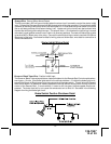
GREEN Wire: Ignition 2 Output
Connect this wire to the ignition 2 wire from the ignition switch. This wire will show + 12 volts when the ignition
key is turned to the "ON" or "RUN" position and is some cases the "START" or CRANK" position. This wire
will show 0 volts when the key is turned to the "OFF" and "ACCESSORY" positions.