


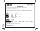
128-7857
4 of 24
4
This Remote Start/Alarm System is designed to be used with Automatic Transmission Vehicles Only!
The unit provides a selectable ignition control that allows a number of selectable timed outputs for glow plug pre-
heat which may be required for certain diesel vehicles, (see selectable feature #9)
. If the diesel engine has a
instant fire, (no glow plug pre-heat system), feature #9 should remain in the default Gasoline mode setting.
For diesel applications, consult your dealer for the type of ignition system used in your particular vehicle.
Regardless of the vehicle, Gasoline or Diesel, for every installation, the vehicle MUST HAVE a Tach Signal
Input, and an Automatic Transmission.
INSTALLATION OF THE MAJOR COMPONENTS:
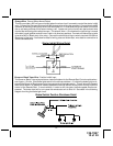
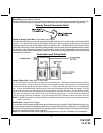
CONTROL MODULE:
Select a mounting location inside the passenger compartment (up behind the dashboard). The mounting
location selected must be within 24" of the ignition switch wiring harness to allow connection of the 6 pin main
wiring harness.
Be certain that the chosen location will not interfere with proper operation of the vehicle. Avoid mounting the
module to or routing the wiring around the steering shaft/column, as the module or wiring may wrap around or
block the steering wheel preventing proper control of the vehicle. Secure the module in the chosen location
using cable ties or screws as necessary.
Do Not Mount The Module In The Engine Compartment, as it is not waterproof.
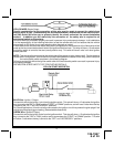
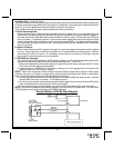
SIREN:
Select a location in the engine compartment that is not accessible from below the vehicle. The selected
location must be clear of hot or moving parts within the engine compartment The siren must be pointed
downward to prevent water retention and the flared end must be pointed away from and out of the engine
compartment for maximum sound distribution. Before securing the siren, check behind your chosen location
to assure that the mounting screws will not penetrate any factory wiring or fluid lines. Secure the siren
mounting bracket using #8 self taping screws or by first using the mounting bracket as a template, scribe or
mark the mounting holes. Drill the marked holes using a 1/8" drill bit, then mount the siren using #8 sheet
metal screws.
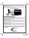
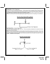
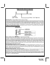
HOOD AND TRUNK PIN SWITCHES:
The pin switches included in this package are intended for protecting the hood and trunk areas of the vehicle.
In all cases, the switch must be mounted to a grounded metal surface. When the pin switch is activated,
(hood/trunk open), it will supply a ground to the input wire activating the alarm. In addition, the hood switch
is required for the safety shut down of the remote start unit. If the vehicle is being worked on, this hood switch
prevents the remote start activation even if the RF command to start is issued. This switch must be installed
in all applications Failure to do so may result in personal injury or property damage. Mount the switches in
the hood and trunk locations away from water drain paths. If necessary, the included brackets may be used
to move the switch away from rain gutters or allow mounting to the firewall behind the hood seal. In both
cases the switch must be set up to allow the hood or trunk door to depress the switch at least 1/4 inch when
the hood or trunk is closed and fully extended when the hood or trunk is opened. For direct mounting, a 1/4
inch hole must be drilled. Carefully check behind the chosen location to insure the drill will not penetrate any
existing factory wiring or fluid lines. Drill a 1/4" hole in the desired location and thread the pin switch into it
using a 7/16" nut driver or deep well socket. If using the mounting bracket, first secure the bracket to the
desired location and secure the pin switch in the pre-threaded mounting bracket hole.
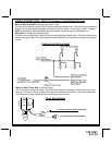
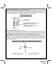
PUSHBUTTON LED SWITCH
Select a mounting location known and accessible to the operator of the vehicle. A dash knockout plug or
front dash panel is desirable as the now Push-Button LED assembly needs the LED to be visible from the
outside of the vehicle and will be used for valet modes, programming features, programming transmitters, and
for overriding the remote start unit when the vehicle is being serviced. Inspect behind the chosen location to
insure that adequate clearance is allowed for the body of the switch, and also that the drill will not penetrate
any existing factory wiring or fluid lines. Drill a 5/16" or 8mm hole in the desired location and mount the switch
by passing the connectors, one at a time, through the panel from the front side and pressing on the bezel until
the switch is fully seated.