


128-7857
20 of 24
20
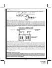
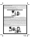
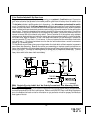
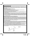
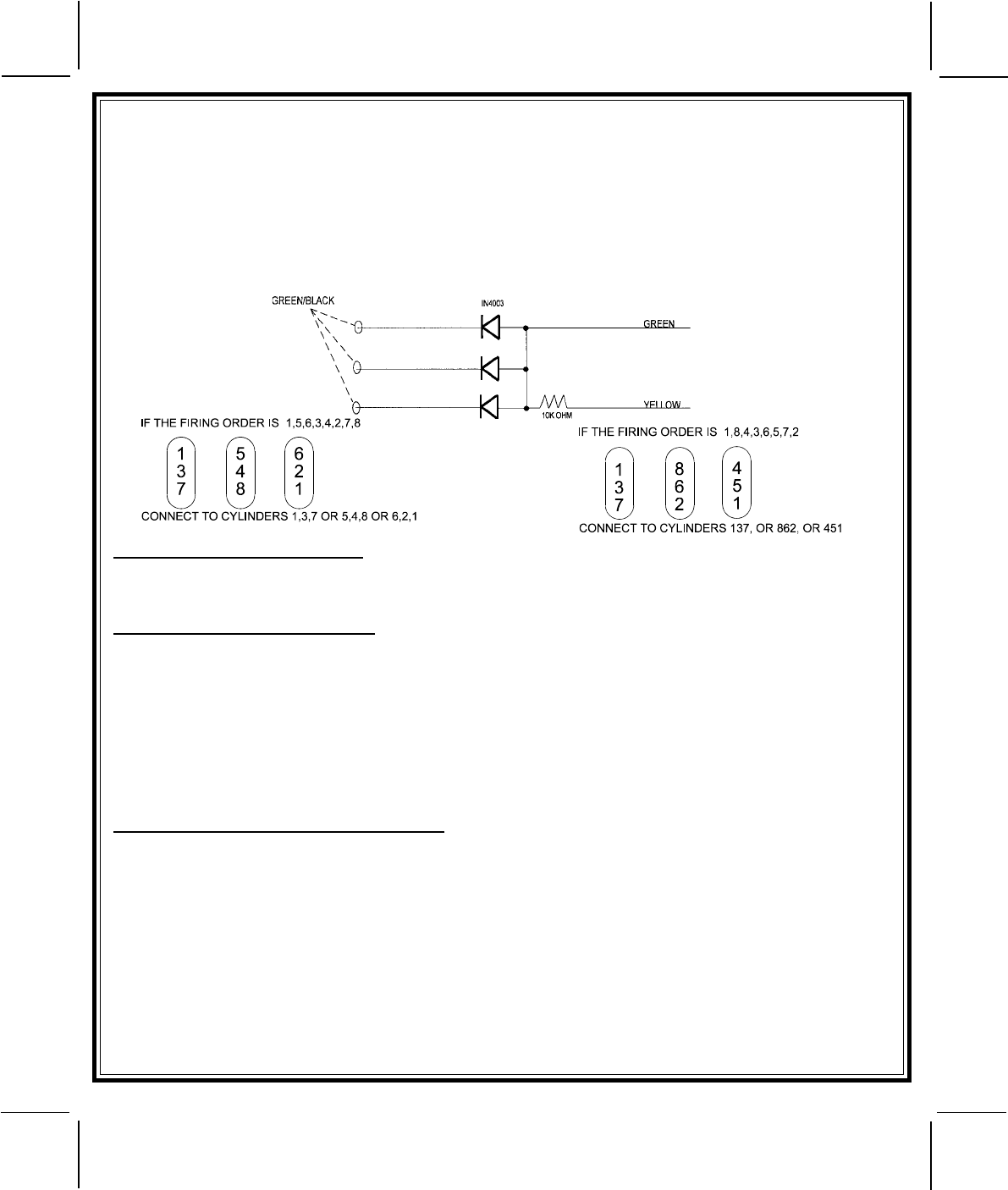
To use the adaptor, the Green/Black wires must connect to the negative side of the ignition coil(s).
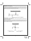
1. For vehicles utilizing independent coils per cylinder, connect the three Green/Black leads to alternate
coils. To achieve optimum performance the coil signals must be evenly distributed. This is accomplished
by first mapping out the firing order of the engine in groups of as indicated below. Draw a circle around any
of the columns. The Green/Black wires should be connected to the negative (-) terminal of the respective
cylinder number which appears in any of the circles.
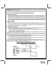
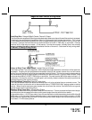
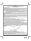
2. For vehicles utilizing 2 cylinder firing per coil pack, connect Green/Black to the tach side of each coil
pack. For 8 cylinder, four coil systems, connect to any of the three coils.
3. Connect the Yellow wire to a +12 volt ignition 1 source. This wire will have +12 volts with the ignition in the
on and start position and have 0 volts with the ignition in the off position.
4. Connect the Green wire to the (Green) or (Orange/Green) tach input of the Audiovox remote start unit.
TESTING YOUR INSTALLATION:
CAUTION!! The following procedure must be performed after the installation of an Audiovox Remote Start
Device. It is the responsibility of the installing technician to complete these tests. Failure to test the unit in
the following manner may result in personal injury, property damage, or both.
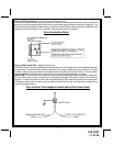
HOOD PIN SAFETY SHUT DOWN:
The intention of the hood pin safety shut down is to prevent the Remote Start unit from being activated while
a mechanic or vehicle owner is performing normal routine vehicle maintenance.
To test the integrity of this circuit:
1. With the drivers window in the down position, start the vehicle using the RF transmitter.
2. Reach inside the car and pull the hood release.
3. Raise the hood and confirm that the remote start unit shuts down.
If the unit fails this test, recheck your pin switch connection to the Gray/Black wire of the Audiovox Remote
Start Unit.
DO NOT RELEASE THIS VEHICLE TO THE CONSUMER UNTIL YOU CONFIRM THE
OPERATION OF THE HOOD PIN SAFETY SHUT DOWN FEATURE.
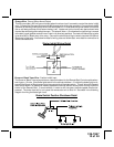
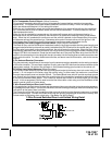
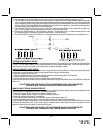
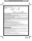
MANUAL SHUT DOWN / ENABLE CIRCUIT:
The intent of the manual shut down / enable circuit is to allow the vehicle operator to prevent operation of the
Remote Start Unit regardless of the RF transmitter operation.
To test the integrity of the manual shut down / enable circuit:
1. Place the control switch in the on (Closed To Ground) position.
2. Start the vehicle using the RF transmitter.
3. The vehicle should start and run under the control of the remote start unit.
4. Move the switch to the off (Open From Ground) position, the vehicle should shut off.
If the unit fails this test, recheck your enable switch connection to the Ground and the Black/White wire of the
Audiovox Remote Start Unit. If you have a plug in enable switch, check that the two pin connector is firmly
seated in the mating connector on the control module.
DO NOT RELEASE THIS VEHICLE TO THE CONSUMER UNTIL YOU CONFIRM THE
OPERATION OF THE MANUAL SHUT DOWN / ENABLE FEATURE.