


128-7857
14 of 24
14
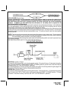
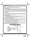
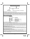
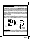
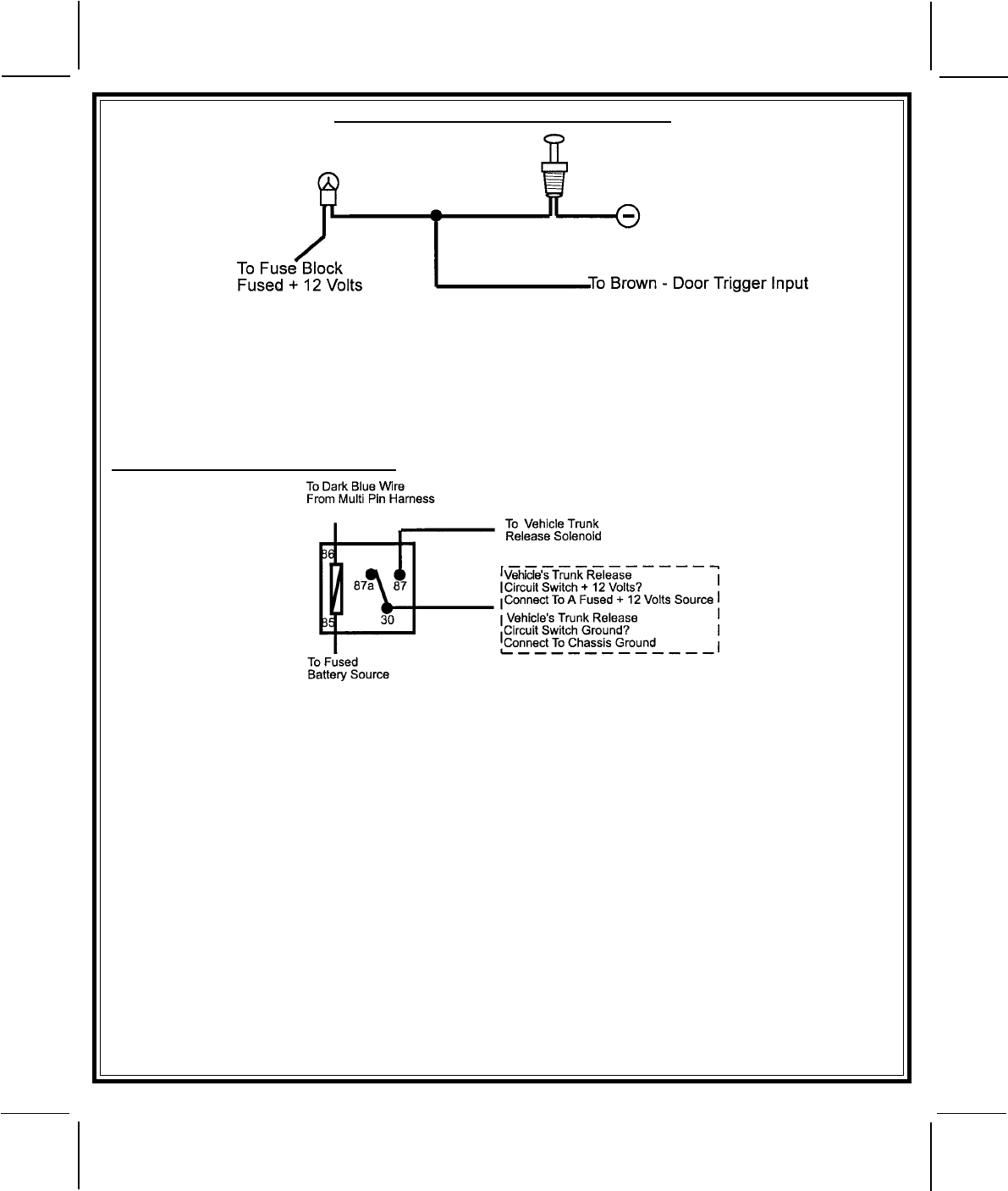
Negative Door Switch Wiring Detail
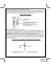
Dark Blue Wire: Delayed 300mA Pulsed Channel 3 Output
The Dark Blue wire supplies a 300mA ground pulsed output whenever channel three of the receiver is accessed.
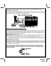
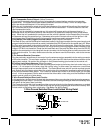
Pressing the pre-programmed transmitter button for three seconds will access channel two. This is a low
current output and must be connected to a relay to supply power to the trunk release or the circuit you wish
to control. Connect the Dark Blue wire to terminal # 86 of a VF45F11 P&B relay or equivalent. Connect
terminal # 85 of the relay to a fused + 12 volt source. Connect the common, normally open, and normally
closed contacts of the relay to perform the selected function of channel 3. See below for relay wiring detail.
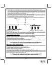
Channel 3 Relay Wiring Detail
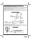
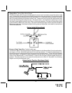
Green w/ Black Trace Wire: 300mA Latched Channel 4 Output
The Green w/ Black Trace wire supplies a 300 mA switched output whenever channel four of the receiver is
accessed. Pressing the pre-programmed transmitter button(s) will access channel four and will remain
active, for up to 8 seconds, as long as the transmitter button(s) is held. This is a low current output and must
be connected to a relay to supply power to the device you intend to control. Connect Green w/ Black Trace
wire to terminal #86 of a VF45F11 P&B relay or equivalent. Connect terminal #85 of the relay to a fused + 12
volt source. Connect the common, normally open, and normally closed contacts of the relay to perform the
selected function of the channel 4 output.
Dark Blue/Black Trace Wire: External Trigger Input
The Dark Blue/Black trace wire allows the remote start unit to be activated from an external source. The
intent of this wire is to allow the unit to be controlled from a "POSSE/CAR-LINK" paging system or similar
device. When this wire receives a ground pulse, the unit will start the vehicle. Connect this wire to a ground
pulsed output from the controlling circuit.
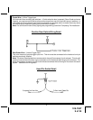
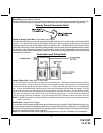
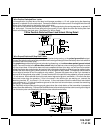
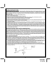
Black w/ White Trace Wire : 300 mA Horn Output
The black w/ white trace wire is provided to beep the vehicle’s horn. This is a transistorized low current output,
and should only be connected to the low current ground output from the vehicle’s horn switch.
If the vehicle uses a + 12 VDC horn switch, then connect the black w/ white trace wire to terminal 86 of the AS
9256 relay ( or an equivalent 30 Amp automotive relay ), and connect relay terminal 85 to a fused + 12 VDC
battery source. Connect relay terminal 87 to the vehicle’s horn switch output, and connect relay terminal 30
to a fused + 12 VDC battery source.