


128-7857
13 of 24
13
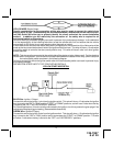
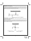
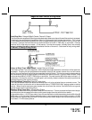
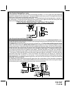
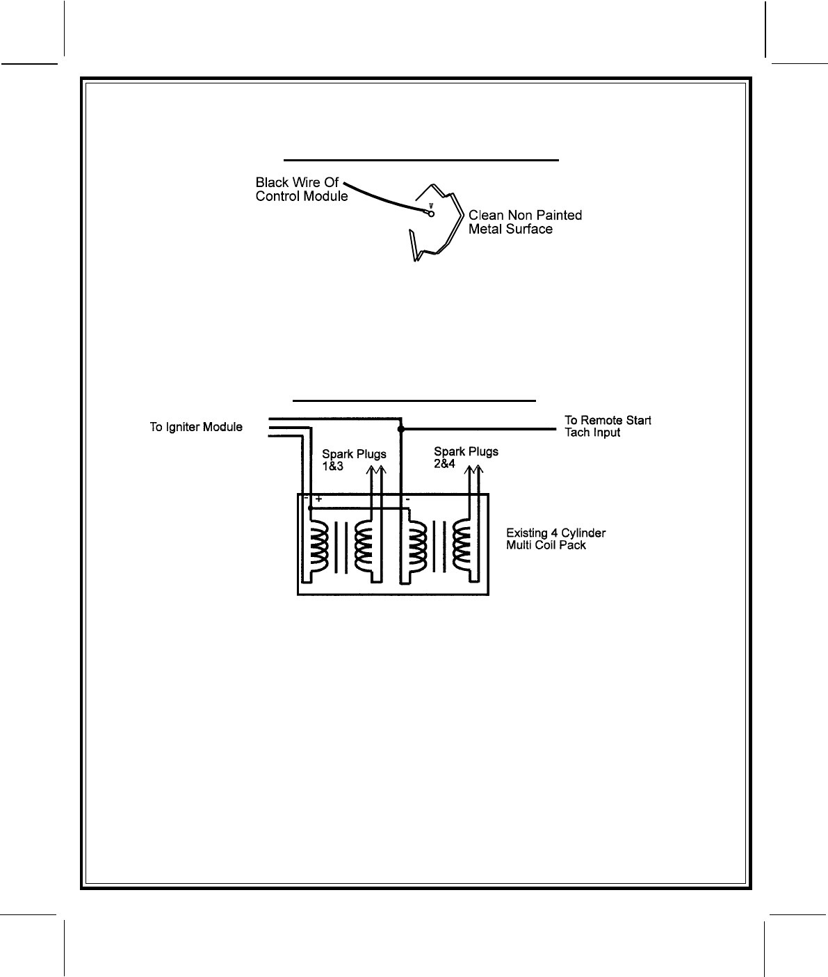
Black Wire: Chassis Ground Source
Connect the Black wire to a known vehicle ground source or to a solid clean metal part of the chassis. Be
certain to remove any paint or grease and secure this wire with a self taping screw and ring terminal.
Chassis Ground Connection Detail
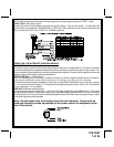
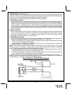
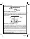
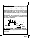
Green w/ Orange Trace Wire: Tachometer Input Signal
This wire will continually monitor the engine's tach rate while the unit is under power of the Remote Start
module. This wire will be routed to the vehicle ECM tach input or through the firewall into the engine
compartment and connect to the negative side of the ignition coil. This Remote Start unit learns the tach
rate of the vehicle and in most cases will operate properly from one multi coil pack regardless of the number
of cylinders. If the vehicle has a single coil unit for each cylinder, it may be necessary to connect this wire
to more than one cylinder for proper tach reference. See multi coil wiring detail shown later in this manual
for additional information.
Tachometer Input Wiring Detail
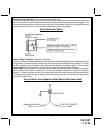
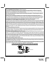
Green/Yellow Wire: Diesel Wait To Start Input
The Green/Yellow wire will connect to a diesel vehicles glow plug wire. When the unit receives a start command,
this wire must go to + 12 then to ground to allow the crank sequence to begin. When ignition #1 is activated by the
remote start unit, the glow plug circuit gets energized, (+ 12 volts), when the glow plug circuit of the vehicle drops
the + 12 volts, which effectively grounds the wait to start input, then 500mS later the starter will engage. This wire
can also be connected to the Glow Plug Bulb wire in the vehicle if this bulb wire gets + 12 volts when the ignition
comes on and drops low when the glow plug circuits temperature is reached. Be sure to fuse the wire with a 1 Amp
Fuse when connecting to a high current circuit such as a factory glow plug wire. The fuse should be installed as
close to the high current wire as possible. If you are installing this unit in a Gasoline vehicle, this wire is not used.
NOTE: If the Glow Plug sense wire, Green/Yellow is connected, this wire will have priority over the setting of feature
Bank 3 Feature #11.
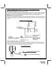
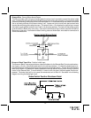
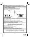
Brown Wire: Negative Door Trigger
If the vehicle's door courtesy light switches ground when the door is opened, (Most GMs and Imports), you
must connect this wire to the negative output from one of the vehicle's door pin switches. In most cases the
Brown wire will need to be connected to only one door switch no matter how many doors the vehicle has as
most door lighting circuits are wired in parallel.
Note: For vehicles with interior delay lighting see programming under title "Completing The Installation".