


128-7857
17 of 24
17
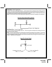
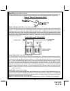
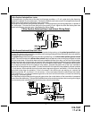
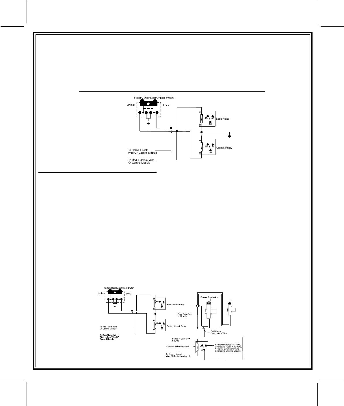
3 Wire Positive Switched Door Locks:
In this application, the Red wire of the door lock harness provides a + 12 volt pulse during the disarming
sequence, or pulsed 12 volt unlock output. Connect the Red wire to the low current 12 volt signal wire from the
factory door unlock switch to the factory door unlock relay.
The Green wire of the door lock harness provides a + 12 volt pulse during the arming sequence, or pulsed 12
volt lock output. Connect the Green wire to the low current 12 volt signal wire from the factory door lock
switch to the factory door lock relay. See Below For Wiring Detail.
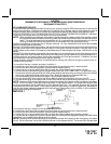
3 Wire Positive Switched Door Lock/Unlock Wiring Detail
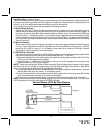
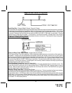
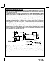
3 Wire Ground Switched 2 Step Door Locks
In this application, the red wire provides a ground pulse during arming, or the pulsed ground lock output.
Connect the red wire to the wire that provides a low current ground signal from the factory door lock switch to
the factory door lock control relay.
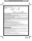
The green wire provides the first ground pulse during disarming, or the drivers door pulsed ground unlock
output. Connect this wire to the drivers door unlock relay that requires a low current ground signal to unlock
only the drivers door. If the vehicle does not have a separate drivers door relay, one will have to be added.
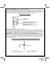
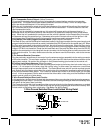
Locate the drivers door unlock motor wire and cut it at a convenient location to allow wiring of an optional relay.
Connect the door side of the cut wire to terminal 30 of the optional relay added. Connect the vehicle side of
the cut wire to terminal 87a of the optional relay added. Connect the green wire of the 3 pin harness to
terminal 86 of the optional relay added. Connect terminal 85 of the optional relay added to a fused constant
+ 12 volt source. Most vehicles door lock/unlock motor legs rest at ground, and switch +12 volts to the door
lock/unlock motor legs for operation, if this is the case in the vehicle you are working on, connect the
remaining terminal, 87, to a fused + 12 volt source. In the rare instance that the vehicle door lock/unlock
motor legs rest at + 12 volts and switches ground to the door lock/unlock motors, connect the remaining
terminal, 87, to chassis ground.
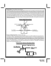
The Red/Black wire provides a pulse ground output when the unlock button of the transmitter is pressed a
second time after disarming. Connect the Red/Black wire to the wire that provides a low current ground signal
from the factory door unlock switch to the factory door unlock control relay.