


128-7857
15 of 24
15
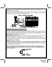
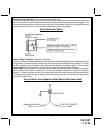
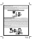
WIRING THE 4 PIN AUXILIARY OUTPUT HARNESS
The auxiliary 4 pin connector provides low current outputs to control various functions in the vehicle during
different stages of the Remote Start unit's operation. Understanding these outputs and the time in which they
occur will allow you to determine if they are needed for the particular vehicle you are working on as well as how
to use them.
Black w Blue Trace Wire: Pulsed Ground Output Before Start
The Black w/ Blue Trace wire will provide a 1 second 300 mA pulsed ground output 1.5 second before the
remote start unit activates as well as when the transmitter is used to disarm the system. Typical use for this
output would be to disarm a factory theft deterrent system to prevent false triggering of the factory alarm when
the remote start unit engages or when the 785 is used to unlock the doors.
Black w/ Light Green Trace Wire: Pulsed Ground Output After Start
The Black w/ Light Green Trace wire will provide a 1 second mA pulsed ground output after the vehicle is
started under control of the remote start unit. Typically this wire will be used to re-lock the vehicle doors if the
doors unlock automatically when the factory anti-theft system is disarmed.
Black w/ Red Trace Wire: Pulsed Ground Output After Shutdown
The Black w/ Red Trace wire will provide a 1 second 300 mA pulsed ground output after the remote start unit
shuts down. This output will occur regardless of whether the circuit times out or is manually terminated.
Typically this output will be used to re-lock the vehicle doors if the doors unlock automatically when the
ignition circuit transitions to off.
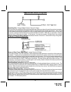
Black w/ Yellow Trace Wire: Ground Output During Start (Crank)
The Black w/ Yellow Trace wire will provide a 300 mA ground output while the starter output of the remote start
unit is active. This output can be used to activate the Crank Low/Bulb Test wire found in some GM vehicles.
This wire is also referred to as the ECM wake up wire in some vehicles.
NOTE: The outputs above are low current outputs and must be used with a relay if the circuit's requirement
is more than 300mA.
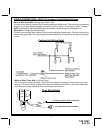
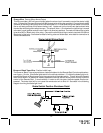
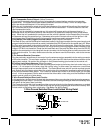
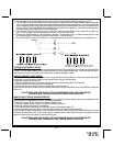
3 Pin Auxiliary Outputs 5, 6, & 7
Lt Blue/Green Wire : DELAYED 300 mA PULSED OUTPUT / CHANNEL 5
The light blue/green wire pulses to ground via an independent RF channel from the keychain transmitter. This
is a transistorized, low current output, and should only be used to drive an external relay coil.
WARNING: Connecting the light blue/green to the high current switched output of trunk release circuits, some
remote start trigger inputs, will damage the control module.
Connect the light blue/green to terminal 86 of the AS - 9256 relay (or equivalent 30 A automotive relay) and wire
the remaining relay contacts to perform the selected function of channel 5.
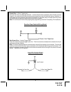
Lt Blue/Black Wire : DELAYED 300 mA PULSED OUTPUT / CHANNEL 6
The light blue/green wire pulses to ground via an independent RF channel from the keychain transmitter. This
is a transistorized, low current output, and should only be used to drive an external relay coil.
WARNING: Connecting the light blue/black to the high current circuits, will damage the control module.
Connect the light blue/black to terminal 86 of the AS - 9256 relay (or equivalent 30 A automotive relay) and wire
the remaining relay contacts to perform the selected function of channel 6.
Blue/Red Wire : DELAYED 300 mA PULSED OUTPUT / CHANNEL 7
The light blue/red wire pulses to ground via an independent RF channel from the keychain transmitter. This is
a transistorized, low current output, and should only be used to drive an external relay coil.
WARNING: Connecting the light blue/red to the high current circuits, will damage the control module.
Connect the light blue/red to terminal 86 of the AS - 9256 relay (or equivalent 30 A automotive relay) and wire
the remaining relay contacts to perform the selected function of channel 7.
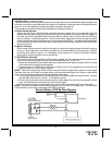
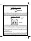
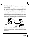
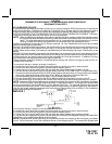
4 Pin Shock Sensor: (White Connector)
The Red (+12 volt), Black (ground), Blue (pre-detect) and Green (full trigger when armed) wires loaded into the
white connector shell are the inputs/outputs of the shock sensor. Route the 4 wire harness from the shock
sensor to the remote start control unit and plug the 4 pin white connector into the mating 4 pin connector shell
of the control module.
Note: While operating under the control of the remote start unit the shock sensor will be shunted (bypassed).
Once the remote start shuts down, the shock sensor will be re-enabled.