


12 © 2003 Directed Electronics, Inc. Vista, CA
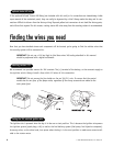
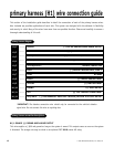
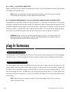
primary harness (H1) wire connection guide
This section of the installation guide describes in detail the connection of each of the primary harness wires.
Also included are possible applications of each wire. This system was designed with the ultimate in flexibility
and security in mind. Many of the wires have more than one possible function. Please read carefully to ensure a
thorough understanding of this unit.
______
______
______
______
______
______
______
______
______
______
______
______
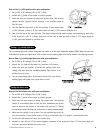
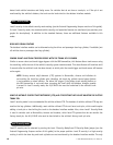
*IMPORTANT! The databus connection wire should only be connected to the vehicle’s databus
signal wire. Do not connect this wire to anything else.
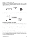
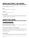
H1/1 ORANGE (-) GROUND-WHEN-ARMED OUTPUT
This wire supplies a (-)500 mA ground as long as the system is armed. This output ceases as soon as the system
is disarmed. The orange wire may be wired to an optional DEI
®
8618 starter kill relay.
primary harness connection descriptions
RED/WHITE (-) PROGRAMMABLE AUXILIARY CHANNEL/DELAYED ACCESSORY OUTPUT
RED (+) 12V CONSTANT POWER INPUT
BROWN (+) SIREN OUTPUT
YELLOW (+) IGNITION INPUT
BLACK (-) CHASSIS GROUND INPUT
OPEN NO WIRE
BLUE (-) INSTANT TRIGGER INPUT, ZONE 1
YELLOW/BLACK* DATABUS CONNECTION
BROWN/BLACK (-) 200 mA HORN HONK OUTPUT
WHITE/BLUE (+) TRUNK RELEASE, SENSOR SHUNT INPUT
WHITE (-/+) SELECTABLE LIGHT FLASH OUTPUT
ORANGE (-) 500 mA GROUND-WHEN-ARMED OUTPUT
H1/1
H1/2
H1/3
H1/4
H1/5
H1/6
H1/7
H1/8
H1/9
H1/10
H1/11
H1/12
primary harness diagram