


8
XNAV9525 GPS NAVIGATION SYSTEM
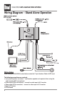
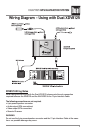
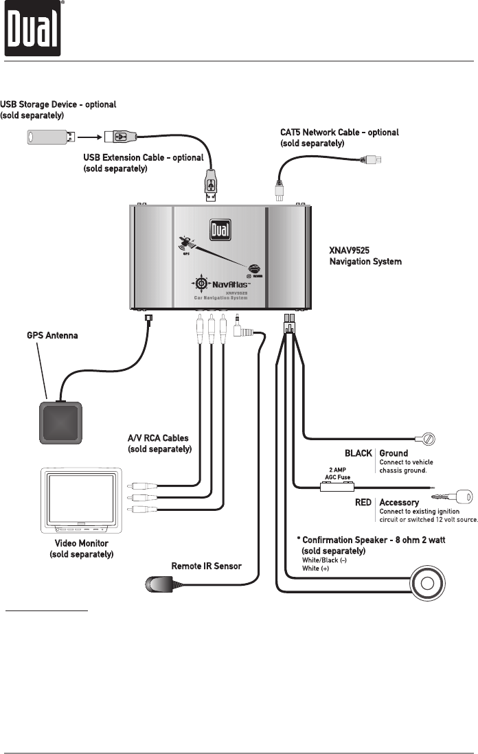
Wiring Diagram - Stand Alone Operation
Wiring Notes
When using the XNAV9525 in stand alone mode, the 13 pin Interface Cable is NOT used.
The following connections are required:
• 4 pin power/speaker connector - *confirmation speaker not required when using the
audio outputs (RCA connections).
• Audio output (RCA connections) - connect to audio input of A/V monitor
• Video output (RCA connection) - connect to video input of A/V monitor
• Remote IR sensor
• GPS antenna