


HY13-1518-M1/USA
Low Speed High Torque, Hydraulic Motors
TK Series
Parker Hannifin Corporation
Hydraulic Pump/Motor Division
Greeneville, TN 37745 USA
Hydraulics
24
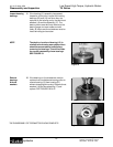
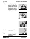
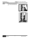
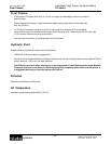
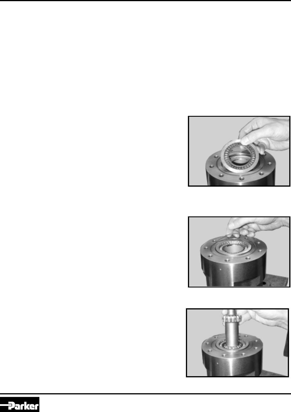
Install
drive link
NOTE
11. Install drive link (11) with the long splined end
down into the coupling shaft (14) and engage
the drive link splines into mesh with the
coupling shaft splines. SEE FIGURE 36.
Use any alignment marks put on the
coupling shaft and drive link before
disassembly to assemble the drive link
splines in their original position in the
mating coupling shaft splines.
Figure 36
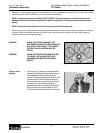
CAUTION
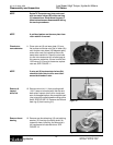
The outer bearing (22) is not lubricated by the
system’s hydraulic fluid. Be sure it is thoroughly
packed with the recommended grease, Parker Gear
grease specification #045236, E/M Lubricant #K-
70M or Mobil Mobilith SHC ® 460 A packet of
grease (P/N 406018) is included in each seal kit.
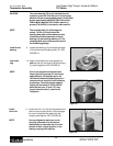
NOTE The coupling shaft (14) will be approxi-
mately .10 inch (2.54 mm) below the
housing wear plate surface when correctly
installed to allow the assembly of thrust
bearing (13) and retaining washer (12). The
coupling shaft must rotate smoothly on the
thrust bearing package.
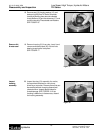
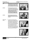
Install thrust
bearing
9. Install thrust bearing (13) and retaining washer
(12) onto the end of coupling shaft (14). SEE
FIGURE 34.
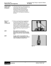
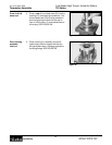
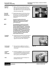
Insert seal
ring
10. Apply a small amount of clean grease to a
new seal ring (5) and insert it into the housing
(21) seal ring groove. SEE FIGURE 35.
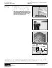
NOTE One or two alignment studs screwed
finger tight into housing (21) bolt holes,
approximately 180 degrees apart, will
facilitate the assembly and alignment of
components as required in the following
procedures. The studs can be made by
cutting off the heads of 3/8-24 UNF 2A
bolts that are over .5 inch (12.7 mm)
longer than the bolts (1) used in the
Torqmotor.
Figure 34
Figure 35
Torqmotor Assembly