


HY13-1518-M1/USA
Low Speed High Torque, Hydraulic Motors
TK Series
Parker Hannifin Corporation
Hydraulic Pump/Motor Division
Greeneville, TN 37745 USA
Hydraulics
16
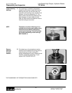
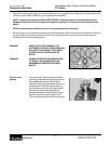
NOTE Series TK Torqmotor may have a rotor set
with two stator halves (9B) with a seal ring
(5) between them. Discard seal ring only if
stator halves become disassembled during
the service procedures.
NOTE A polished pattern on the wear plate from
rotor rotation is normal.
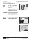
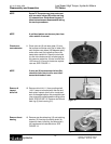
Check rotor,
vane clearance
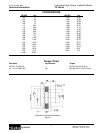
11. Place rotor set (9) and wear plate (10) on a
flat surface and center rotor (9a) in stator (9b)
such that two rotor lobes (180 degrees apart)
and a roller vane (9c) centerline are on the
same stator centerline. Check the rotor lobe
to roller vane clearance with a feeler gage at
this common centerline. If there is more than
.005 inches (0.13 mm) of clearance, replace
rotor set. SEE FIGURE 11.
NOTE If rotor set (9) has two stator halves (9b),
check the rotor lobe to roller vane clear-
ance at both ends of rotor.
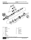
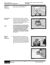
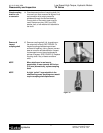
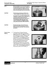
Remove &
inspect
drive link
12. Remove drive link (11) from coupling shaft
(14) if it was not removed with rotor set and
wear plate. Inspect drive link for cracks and
worn or damaged splines. No perceptible lash
(play) should be noted between mating spline
parts. SEE FIGURE 12. Remove and discard
seal ring (5) from housing (21).
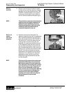
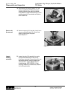
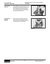
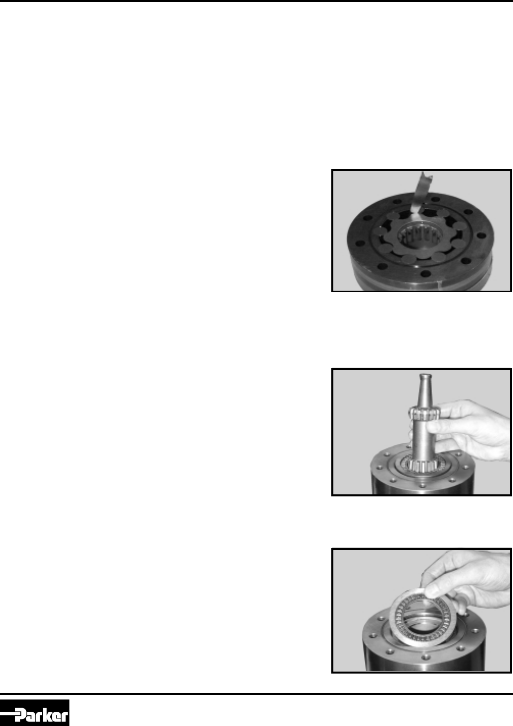
Remove thrust
bearing
13. Remove rear thrust bearing (13) and retaining
washer (12) from top of coupling shaft (14).
Inspect for wear, brinelling, corrosion and a
full complement of retained rollers. SEE
FIGURE 13.
Figure 13
Figure 12
Figure 11
Disassembly and Inspection