


7
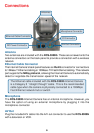
DC Power Connector
The DC power input connector is located on the DCS-5300G Internet Camera’s
back panel and is labeled 12VDC with a single socket to supply power to the
Internet Camera.
I/O Connector
The DCS-5300G provides a terminal block with two pairs of connectors situated
on the back panel. One pair is for input and the other is for output. The I/O
connectors provide the physical interface to send and receive digital signals to
a variety of external alarm devices. Please refer to the Appendix (Page 132)
in this manual for detailed information.
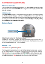
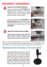
Connections (continued)
Located on the bottom panel of the Internet Camera, the socket is used to
connect the camera stand to the Internet Camera by attaching the screw head
on the camera stand to the Internet Camera.
Bottom Panel
Socket for stand
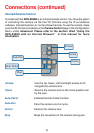
Power LED
LED stands for Light-Emitting Diode.
The Power LED is positioned to the right of the Internet Camera lens. As soon
as the power adapter is connected to the Internet camera the power LED will
flash red and green several times, the DCS-5300G is conducting a self-test.
Upon passing the self-test the LED will turn green to indicate a good connection
to an Ethernet port or red to indicate no connection has been made.
Attachment socket for the Camera Stand