


133
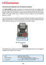
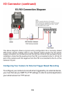
The above diagram shows a typical wiring configuration for a normally closed
PIR motion sensor. Please refer to your specific motion sensor for the power
supply connection to the device since this will be critical to the success of your
installation. Note that the positive from the PIR is connected to the D- of the I/O
port of the camera and the negative from the PIR is connected to the D+ of the
camera I/O port.
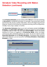
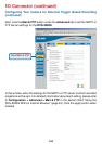
Configuring Your Camera for External Trigger Based Recording
I/O Connector (continued)
To configure your camera to record when triggered by an external device,
you must first set your SMTP or FTP settings in order to send snapshots to
your email account or FTP server.