


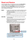
132
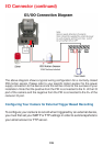
I/O Connector Definition for the Internet Camera
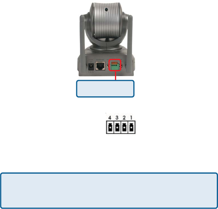
The DCS-5300G provides a general I/O terminal block with one digital input
and one relay switch for device control. Pin 1 and pin 2 can be connected to an
external sensor and the state of voltage will be monitored from the initial state
‘LOW’. The relay switch of pin 3 and pin 4 can be used to turn the external
device on or off.
The I/O connector provides the physical interface for digital output (DO) and
digital input (DI) that is used for connecting a diversity of external alarm devices
to the Internet Camera such as IR-Sensors and alarm relays.
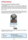
I/O Connector
The digital input is used for connecting external alarm devices and once triggered
images will be taken and e-mailed.
1 DI+ INPUT (Max. 50mA, 12VDC)
2 DI- INPUT (Initial state of DI is low)
3 SW_COMMON OUTPUT (open from SW_OPEN at initial state)
(close with SW_OPEN when set DO to ON)
4 SW_NOPEN OUTPUT (Max. 1A, 24VDC or 0.5A, 125VAC)
I/O Terminal Block:
I/O Connector