


10 © 1999 Directed Electronics, Inc.Vista, CA
N430 9/99
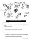
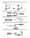
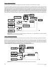
H1/5 GREEN
(-) door trigger or
H1/7 VIOLET
(+) door trigger input: If the door switch wire you found is (-) when the
door is open, connect the GREEN wire to it. If the door switch wire you found is (+) when the door is open, use the
VIOLET wire instead.
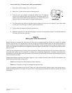
IMPORTANT! Test to make sure this wire "sees" all doors!
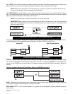
H1/6 BLUE
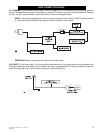
(-) instant trigger:This input will respond to a (-)input with an instant trigger. It is ideal for hood and trunk pins and will
report on zone one. If connecting several inputs to this wire.They Should be diode isolated as shown below
.
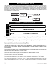
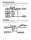
H1/8 BLACK
(-) chassis ground connection. Connect this wire to bare metal, preferably with a factory bolt rather
than your own screw (screws tend to either strip or loosen with time). We recommend grounding all your compo-
nents to the same point in the vehicle.
H1/9 YELLOW
(+) ignition input. Connect this wire to an ignition wire as described on page 5. This wire must show
+12V with the key in run position and during cranking.Take great care that this wire cannot be shorted to the chassis
at any point.
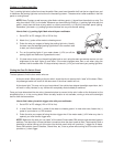
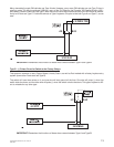
H1/10 BROWN
(+) siren output: Connect this to the red wire of the Revenger
®
siren. Connect the black wire of the
siren to (-) chassis ground, preferably at the same point you grounded the control module’s H1/8 BLACK wire.
NOTE: REMOVE ANY PAINT
BELOW RING CONNECTOR