


17
© 2006 Directed Electronics
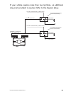
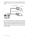
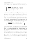
If the GREEN wire is being used for ign2 an additional relay (not
provided) is required for a 2nd accessory. Refer to the diagram
below.
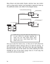
Now that the accessories have been located, find the suspected
starter wire according to the web information. Leave the black
lead of your tester on ground and place the red lead of your multi-
meter on this wire. The multimeter should read 0 volts in all key
positions except the crank position. In the crank position your
multimeter should read 12 volts, and will go to 0 volts when the
starter disengages.
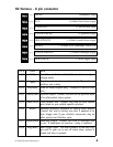
87
87A
86
85
30
+12 VDC CONSTANT (FUSED 20A)
GROUND
TO 2
nd
ACCESSORY
WHITE (+) 30A OUTPUT TO
ACCESSORY CIRCUIT
TO ACCESSORY
2
nd
ACCESSORY RELAY
(NOT PROVIDED)
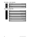
87
87A
86
85
30
+12 VDC CONSTANT (FUSED 20A)
GROUND
TO ACCESSORY
ACCESSORY RELAY
(NOT PROVIDED)