


14
© 2006 Directed Electronics
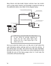
With the key in the off position, test the suspect wire. The
constant power wire will read 12V on the multimeter. Once the
constant power wire has been identified, solder the two heavy
gauge 12 VOLT wires (PINK) from the control module to it and
wrap the connection with electrical tape.
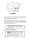
Testing for Ignition Wires
With the multimeter lead still connected in the kick panel, locate
the suspected ignition wire. It will test differently than constant
12 volts. Place the red lead of the multimeter on the suspected
wire. With the key in the off position the multimeter will read 0.
Turn the key to the on position and the multimeter will read 12
volts. Now, watching your multimeter, turn the key to the crank
position. If the 12 volts stays on, then you have found your igni-
tion wire. If the wire tests correctly, solder the BLUE heavy gauge
wire to it and wrap the connection with electrical tape.
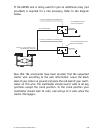
If the vehicle requires more than one ignition as per the web site
information, follow the same test procedure and solder the GREEN
heavy gauge wire to it then wrap the connection with electrical
tape. If your vehicle has only one ignition wire, secure the GREEN
wire and dress it out of the way.
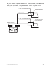
note! If the vehicle has more than one constant
power wire, utilize two of them. Connect one of the
heavy gauge PINK wires to one of the constant
power wires and the other heavy gauge PINK wire to
the other constant power wire.