


MAN 650067:F
32
Setting the time & temperature unit:
The remote function switch is used for adjusting the time, day, and date. At any time during the setup you
can turn the key off and all of the changes you made will be saved. The next time the key is turned on the display
will light up normally.
1. To enter the set mode, hold the switch in while turning the key on. The gauge will display the time, day of
week, and temperature unit with the minutes selected.
2. Press and release the switch to increment the minutes. Press and hold the switch in to move to the hours.
3. While the hours are selected, press and release the switch to increment it. Press and hold the switch to
move to the day of week.
4. While the day of week is selected, press and release the switch to increment it. Press and hold the switch
to move to the temperature setup.
5. While the temperature unit is selected, press and release the switch to change it. Press and hold the
switch to move to the date setup.
6. The year, date, and month will be displayed with the year selected. Press and release the switch to
increment the years. Press and hold the switch in to move to the month.
7. While the month is selected, press and release the switch to increment it. Press and hold the switch to
move to the date.
8. While the date is selected, press and release the switch to increment it. Press and hold the switch to move
to the time adjustment.
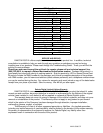
9. The display will now show a number from -7 to +7. This is the current time adjustment setting. Pressing
and releasing the switch will increment the value. A setting of zero does no adjustment, +2 adds two
seconds per day (slows the clock down), -3 subtracts three seconds per day (speeds the clock up), and so
forth. When the desired adjustment setting is displayed, press and hold the switch. The clock will now
restart in its normal display mode.
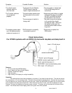
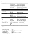
TEMPERATURE SENSOR CONNECTION
The sender must be Dakota Digital part SEN-15-1. Sending units from other manufacturers will cause
incorrect readings. The red wire on the sensor connects to the gray wire on the clock. The black wire connects to
the black wire or the case of the clock.
The sensor will measure the temperature where its probe is located. The sensor has a 12’ two-wire cable
to connect it to the gauge. This cable can be shortened or additional wire can be added. If additional wire is
added, the added wire pair should be twisted and polarity of the wires should be carefully noted. If the probe
temperature is below -39° the display will show “- - -“. If a sender is not connected properly, the temperature
display will not be available. If the SND terminal is shorted to ground, the display will show “---”.
For outside temperature sensing, the best location will be in the front grill or another location at the front of
the vehicle where it will have good air flow while the vehicle is moving. Do not mount the sensor too close to the
engine or exhaust. Doing so will cause the temperature reading to be much higher than the actual outside
temperature. Please note that with the sensor mounted in the front grill the temperature will be very accurate while
the vehicle is moving, but the temperature will rise when the vehicle is sitting still. This is due to the engine heat
radiating forward.
For inside temperature sensing, keep the sensor away from heating and A/C vents. Having these blowing
on the sensor will cause inaccurate readings of the actual vehicle cabin temperature. Also, keep the sensor away
from any heat generating electrical components.
The air temperature gauge will operate and read correctly between the temperature range of -39 - 255° F
(-39 - 125°C).