


4
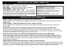
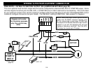
WIRING: 3-Pin (EZ-45DP II) and 5-PIN (EZ-55DP II/95FM II) Connector
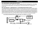
PIN 1: White: (+12V) Brake Reset
Connect the White wire to the side of brake pedal switch that shows +12 volts ONLY when pedal is depressed. This will
turn off the remote start if someone attempts to drive the car without the keys or if the Ignition key is not turned on all the
way.
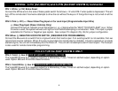
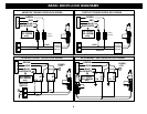
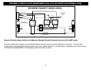
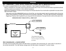
PIN 2: Pink: (+12V) +/- Diesel Glow Plug Input or Car Jack Input (Programmable Input Wire)
+/- Glow Plug Input (Diesel Vehicles Only)
Connect Pink wire to indicator circuit that shows a (- or +) Signal while the “WAIT TO START LAMP” is on. When
this wire is used, the system will wait until light turns off before attempting a remote start. Note: This input is jumper
selectable for Positive or Negative type signals. See Jumper Pin diagram (Pg. 26) for jumper configuration.
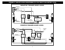
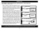
PIN 3:Blue: (-) NEGATIVE HOOD PIN SWITCH (REQUIRED FOR PROGRAMMING)
Connect the Blue wire to a switch that is at ground when the hood is open. If an existing switch is not available, then we
recommend one be installed. When this wire is grounded, the remote start is inhibited. If hood is opened on a remote
started engine, the unit will immediately shut the motor off. The unit will not attempt to start if hood is open. The hood pin
is also used for remote transmitter programming.
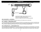
PIN 4/5 FOR EZ-55DP II/95FM II ONLY
PIN 4: Violet: (-) Aux #3 FOR EZ-55DP II AND EZ-95FM II ONLY
The Violet/White wire for a negative output for a Momentary, Pulse, Timed or Latched output, depending on option
used. Option #26 and 27controls these functions.
PIN 5: Violet/White: (-) Aux #4 FOR EZ-55DP II AND EZ-95FM II ONLY
The Violet/White wire for a negative output for a Momentary, Pulse, Timed or Latched output, depending on option
used. Option #26 and 27controls these functions.