


13
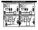
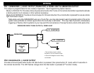
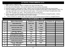
WIRING: 3-PIN CONNECTOR
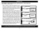
PIN 1: WHITE/RED: TACHOMETER INPUT
When installing the system in Tach mode, this wire must be connected to a valid source of AC voltage. This wire allows
the unit to sense the engine running and control the starter motor. See TACH REFERENCE MODE.
PIN 2: BLACK: MAIN SYSTEM GROUND
Connect to chassis metal of the vehicle. An existing bolt or screw may provide an adequate ground, or drill a small hole,
scrape away paint and attach using a sheet metal screw & star washer. This wire must be connected to a proper ground
or undesirable and inconsistent operation will occur. Do not use Factory ground locations.
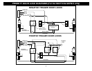
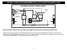
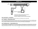
PIN 3: WHITE: +12V or (-) NEGATIVE PARKING LIGHT OUTPUT:
Connect to vehicle parking light circuit at the back of light switch or if this is not possible, connect directly to one of the
parking lights at the front of the vehicle. If your vehicle has a multiplex lighting system that requires a (-) Negative parking
light output, then open the access door on the top of the module and move the jumper. See Jumper Pin section. Some
European vehicles require separate left and right circuits. Use a dual relay or diodes to isolate the output. Note the
current limit on the Negative parking light output. You may require an external relay to prevent damage to the unit.
(1) Default parking light output is +12 volts.
(2) Use an external relay for vehicles that draw excess current from extra running lights, light bars, or trailers.
Parking light output is limited to (+) 10 amps or (-) 500 mA only.
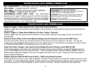
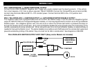
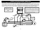
WIRING: 6-PIN HIGH-CURRENT CONNECTOR
BROWN: +12V STARTER OUTPUT 30A:
Connect to circuit in the vehicle that has power ONLY while the STARTER MOTOR is CRANKING.
GRAY: +12V ACCESSORY OUTPUT 30A:
Connect to circuit in the vehicle that provides Accessory Power for systems such as HEAT and A/C. Typically, this wire
turns ON with the first position of the key, DROPS OUT WHEN CRANKING, then returns as the engine starts and runs.
(2) RED: +12V POWER INPUT WIRES (30A Fused):
Connect to both of these leads to +12V Constant Power. We recommend the BATTERY POSTIVE TERMINAL.
PINK: +12V IGNITION OUTPUT 30A:
Connect to circuit in the vehicle that provides true Ignition Power for systems such as Spark and Fuel. Typically, this wire
turns ON with the second position of the key, STAYS ON WHEN CRANKING, and continues ON as the vehicle runs.