


18
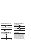
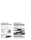
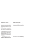
TESTING: Door Locks There are four basic types:
Type A Door Lock Test (Most GMs and some Chryslers)
Probe both of your door lock wires going to the door lock switch usually
located in the drivers kick panel. Attach the clip end of your test light
to a good chassis ground. Using the vehicles door lock controls, activate
the lock then the unlock, testing both wires one at a time. If one of these
TESTING DOOR LOCKS
LOCATING & MAKING
CONNECTIONS
CONT.
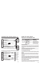
sensor to 22 gauge BLACK wire with green tag. If you add more than
one sensor, a diode must also be added. NOTE: This unit is designed
to use only a single stage sensor. If you are using a dual stage
sensor, use only the major output of the sensor. CAUTION: When
adding more than one perimeter sensor on the same input trip,
you must add a 500ma diode to the output of each sensor.
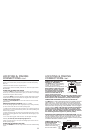
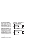
CONNECTING
THE WIRING HARNESS
5. GREEN/WHITE Unlock Input
4. GREEN/BLACK Unlock Output
3. RED/BLACK To source (+) or (-)
DOOR LOCK HARNESS
1. BLUE/BLACK Lock Output
2. BLUE/WHITE Lock Input
FUSE
1. YELLOW Antenna
2. GREY (-) Ch. 3 Output
3. RED/BLACK (+) or (-) Door Pin Input
4. BLACK/WHITE (-) Dome Light Output
5. BLACK/BLUE (+) Siren Output
10. BLACK Ground
9. BROWN (+) Parking Light Output
8. BLUE/BLACK (-) Starter Immobilizer Output
7. YELLOW/BLACK (+) Ignition Input
6. BLUE (-) Ch. 2 Output
FUSE
11. RED (+)
12V Constant
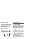
CONNECTING ADDITIONAL SENSORS
NOTE: We suggest adding the optional shock sensor model UTB-
2 for additional protection.
BLUE PLUG
LED
INDICATOR
GROUND
OVER-
RIDE
SWITCH
WHITE
PLUG
22 GA BLACK WIRE WITH GREEN TAG
(Shock or microwave sensor - negative
input), optional accessories required
LOCATING & MAKING
CONNECTIONS
CONT.
Follow the instructions
that come with the
sensors to mount and
power them. The system
requires a negative (-)
output from the sensor for
activation of the alarm.
Connect negative out from
17
Drill a 5/16 inch hole in the mounting surface, taking care not to damage
anything behind the surface.
Remove the switchs top nut and lock washer.
Push the switch into the hole from the back of the mounting surface.
Then secure it with the lock washer and nut.
Connect the ground wire to a metal vehicle body part using an existing
screw.
Plug override switch into the left side of the main header.
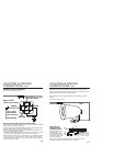
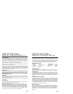
CONNECTING THE DOME LIGHT SUPERVISION
(Optional relay needed,
part #775)
Connect the BLACK/WHITE
wire from the control module
wiring harness to the relay.
Connect the relay to the
dome light wire, normally
found in the drivers kick
panel. NOTE: A relay must
be used to connect the dome
light supervision function.
(-) BLACK/
WHITE
FROM
MODULE
12V (+)
FUSED AT 5
AMPS
87a
(+) OR (-) DEPENDING ON
DOOR TYPE NOTE: IF (+),
FUSE AT 20 AMPS
TO DOME
LIGHT
CIRCUIT
Optional Part #775