


11
LOCATING & MAKING
CONNECTIONS
CONT.
3. Turn the ignition ON. Probe for a wire that shows 12 volts only when the
ignition is on. Confirm this by turning the ignition on and off while probing
each wire.
4. Mark this wire with its function Ignition Power.
5. If these wires cannot be located, please call our technical support staff at
800-878-8007.
CONNECTING THE POWER AND GROUND
1. Connect the RED wire from the harness to a constant 12 volt supply or to
the wire you ran from the positive battery post (if no constant 12 volt supply
was found at the ignition switch harness).
2. Connect the BLACK wire from the harness to a clean chassis ground, usually
a steel automotive body part connected to the negative side of the battery.
CONNECTING IGNITION POWER
1. Connect the YELLOW/BLACK wire from the harness to the wire market
Ignition Power.
FINDING THE PARKING LIGHT WIRE (optional - included)
To have the parking lights flash when using keyless entry or during a violation,
you must connect the 1402 to the vehicles parking lights.
1. Locate the wire harness coming from the back of your vehicles light control.
If the control is on your vehicles steering column, the harness probably joins
several wiring harnesses.
2. Use the vehicles wiring color code to find the parking light wire. Connect
this wire to the parking light wire usually located under the hood going to your
parking lights.
3. Turn on the parking lights. Probe the wires. The test light should light
indicating 12 volts only when the parking lights are on.
4. After you locate the wire, use a piece of masking tape to mark it with its
function (Parking Lights).
CONNECTING THE PARKING LIGHT WIRE
Connect the BROWN wire from the wiring harness to the wire marked Parking
Lights.
LOCATING & MAKING
CONNECTIONS
CONT.
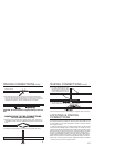
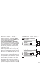
CONNECTING THE NEGATIVE
OUTPUT #1, BUTTON #2
THE BLUE wire is used to operate a
remote car starter, window roll-up
module, etc. for as long as
transmitter Button #2 is depressed.
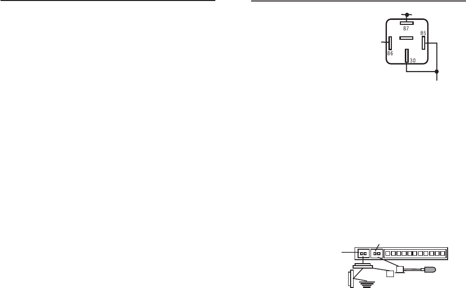
NOTE: A SPST or SPDT relay must
be used if you want to convert
the negative signal to positive
or if the device youre controlling
draws more than 200 ma. If
youre not sure how much
BLUE
87a
12 VOLTS CONSTANT
TO FACTORY TRUNK
WIRE OR OTHER
POSITIVE
ACTIVATED
ACCESSORY
Optional Part #775Optional Part #775
amperage is being drawn, add the relay. This negative output
is only rated for 200 ma (1/5 amp). CAUTION: Overloading
these outputs is not considered a warranty related repair.
CONNECTING THE NEGATIVE OUTPUT #2, BUTTON #3
The GREY wire is used to operate the power trunk release. Press and
release Button #3. The trunk will open and the parking lights will
flash. If the unit is armed (doors locked) you must press and hold
Button #3 for two seconds. The trunk will open and the shock sensor
input (black wire with green tag) will be disabled. The door triggers
will still be active. NOTE: A 30 amp relay must be used since this
negative output is only rated for 200 ma (1/5 amp). Since
most power trunk releases are positive controlled and draw
5 to 6 amps, this relay handles the load and also can convert
the release signal from negative to positive polarity.
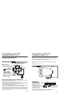
INSTALLING THE FLASHING LED STATUS INDICATOR
(optional)
The LED indicator installs inside your vehicle and should be installed
as high as possible and in view from all windows. Drill a 1/4 inch
mounting hole in the dash panel or use the supplied mounting bracket
to hold the LED status indicator in place.
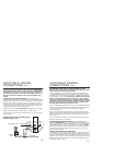
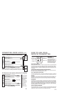
CONNECTING THE LED
STATUS INDICATOR
Plug the LED Status
indicator into the blue plug
between the white plug
and the main header.
BLUE PLUG
LED
INDICATOR
GROUND
OVER-
RIDE
SWITCH
WHITE
PLUG
22 GA BLACK WIRE WITH GREEN TAG
(Shock or microwave sensor - negative
input), optional accessories required