


19
TESTING DOOR LOCKS CONT.
wires tests (+) positive when lock is pressed and the other tests (+)
positive when they are unlocked, your vehicle has a Type A door
locking system. Make sure to mark which wire is lock and unlock. Proceed
to Connecting Door Locks, Connecting Door Locks. NOTE: Type A and
Type C locks will test the same, until you test for ground. Make sure
you run both tests before making your connections.
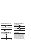
Type B Door Lock Test (Most Imports, some newer Fords)
Probe both of your door lock wires going to the door lock switch usually
located in the drivers kick panel. Attach the clip end of your test light
to +12V. Using the vehicles door lock controls, activate the lock then the
unlock testing both wires one at a time. If the test light illuminates when
you probe the lock and the unlock wires your vehicle has a Type B
door locking system. Make sure to mark which wire is lock and unlock.
Proceed to Connecting Door Locks.
Type C Door Lock Test (Most Fords, some Chryslers, GM Trucks)
(Optional part #778 required)
Using your test light probe both the lock and the unlock wires usually
located in the drivers kick panel. Attach the clip end of your test light
to ground probing both wires one at a time while locking and unlocking
the doors with the drivers side switch (usually the master switch). The
test light should illuminate in both switch positions. Now attach the clip
end of your test light to +12V constant, probe both wires one at a time
again. The light should then illuminate again only in reverse order. This
tells you that you have a Type C reversing polarity system. Make sure
to mark which wire is lock and unlock. Proceed to Connecting Door Locks.
Testing Switch Wire and Motor Wires for Type C Door Locks
Before connecting, you must now determine which wire is the switch wire
and which is the motor wire. Cut both the lock and unlock wires in half.
Start with both of the lock wires by placing the clip end of your test light
to ground, hold the door lock switch in the lock position, make sure you
are using the master switch (usually on the drivers door) and probe both
lock wires looking for voltage. The wire that illuminates the test light,
mark as the switch wire, the wire that shows no voltage, mark as the
motor wire. Repeat the procedure for the unlock wire.
One Wire Door Lock System
Some vehicles have a single switch wire for both lock and unlock. This
system will wire as a Type A or Type B depending on the vehicle. The
only difference being this system will require one or two resistors depending
on the make and model of the vehicle. Please consult our website for the
proper resistor value for your vehicle.
20
CONNECTING DOOR LOCKS
CONT.
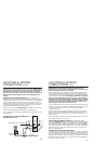
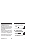
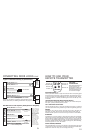
Type B (-) Negative (5-pin harness)
LOCK
UNLOCK
BLUE/BLACK Lock
BLUE/WHITE
Not Used
RED/BLACK
GREEN/BLACK
Unlock
GREEN/WHITE
Not Used
MODULE
Ground
FUSE
NOTE: Connect the RED WITH BLACK STRIPE wire to ground.
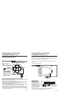
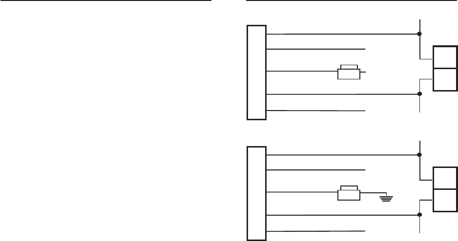
Type A (+) Positive (5-pin harness)
LOCK
UNLOCK
BLUE/BLACK Lock
BLUE/WHITE
Not Used
RED/BLACK
GREEN/BLACK
Unlock
GREEN/WHITE
Not Used
MODULE
+12V Constant
FUSE
NOTE: Connect the RED WITH BLACK STRIPE wire to +12V constant power.