


13
LOCATING & MAKING
CONNECTIONS CONT.
CONNECTING THE MAIN WIRING HARNESS TO THE MODULE
Carefully plug the main harness into the 1402 module. DO NOT plug
the harnesses into the control module until all connections have
been made. Be careful to line up the pins on the unit with the
wiring harness plug (lip up - Red wire to the right). Failure to do
this will cause severe damage to the unit and possibly to the
vehicle.
CONNECTING THE STARTER DISABLE (Part #773 Required)
Locate the cranking wire at the base of the steering column. When testing,
the cranking wire will show 12 DC only when the key is in the cranking
position. Once located, cut the wire in two. Try to crank the engine, it
should not crank. Next, mark both ends of the cranking wire. The wire
running back into the steering column, mark Key Side, and the wire
running toward the engine, mark Starter Side.
Connect the control module BLUE/BLACK wire negative (-) out when
armed to the optional starter disable relay (-) negative input.
Use a wire tie to secure the starter disable relay to a non-moving part
under the dash.
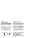
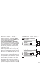
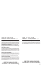
CONNECTING THE STARTER DISABLE WITH
HARNESS (PART #773)
87A
85
86
87
30
FROM ALARM OUTPUT BLUE/BLACK
TO STARTER
IGNITION
CRANKING
WIRE
14
LOCATING & MAKING
CONNECTIONS
CONT.
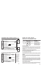
DETERMINING YOUR VEHICLES DOOR PIN SWITCH TYPE
NOTE: For your alarm systems arming feature to work, you must
connect the alarm to the door pin switch.
On some vehicles this wire might also be called a door trigger and is
usually located behind the drivers kick panel. Some vehicles have logic
controlled dome and courtesy lights that turn on differently depending
on which vehicle door is opened. NOTE: Some vehicles such as Honda
have door switch isolation diodes on each door. These vehicles
must be wired at the wire that triggers the dome light circuit after
the diodes. If the door switch wires are difficult to reach, connect
the input wire to the dome light itself. Be sure to locate a wire
that is triggered from all your vehicles doors.
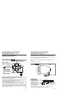
Touch your test lights positive lead to a point on the fuse block that has
constant 12 volts. Use the other lead to probe the control wire. Then open
the door. If the test light turns on, your vehicle has a negative
(-) switch door pin.
Connect your test lights negative lead to a good solid chassis ground.
Use the positive lead or other lead to probe the control wire. Then open
the door. If the test light illuminates, your vehicle has a positive (+)
switch door pin.
Use masking tape to mark the wire with its function Dome Light and
switching type positive or negative.
CONNECTING THE DOOR PIN SWITCH (Programmable option)
Connect the RED/BLACK wire from the module to the wire marked Dome
Light. (Select positive or negative according to the pin switch type when
in programming mode - refer to programming mode, page 25. NOTE:
The door inputs activate 10 seconds after arming. If the 1402 chirps three
times with the door closed, after arming the system, the wrong door
option has been selected.
FINDING THE EXISTING CAR HORN WIRE
The existing car horn wire will usually be found in a harness at the base
of the steering column. Probe for a wire which will remain neutral until
the horn is pressed. When the horn is pressed, the test light will show a
negative pulse or a ground. To be sure that this is the correct wire, simply
pulse the chassis ground to this wire. The horn should sound. Mark this
wire with its function, Horn.