


bühler
1500 Bale Carrier
30
APPENDIX B
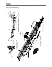
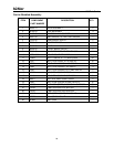
Hydraulic Assembly
NOTE:
1)
Hydraulic Assembly methods and layouts are common to the right and
left sides. Only one side of each component is shown in this manual.
2) Seal Kits and Service Parts are only listed in the parts lists and are not indicated on
the illustrations.
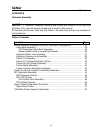
Table of Contents
Description Page
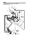
Carrier Hydraulic Assembly Schematic (Standard Configuration). ……………
31
Valve Bank Assembly………….….……………………………………….…....
33
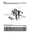
FPS Directional Valve Bank Assembly……………………………………...
35
Series Parallel Valve (Low and High Speed)……………………………….
36
Hydraulic Return Line Assembly………………………………………………..
37
Hydraulic Pressure Line Assembly…………………………………………... 38
Carrier Tilt Assembly……………………………………………………………..
39
Carrier Tilt Cylinders Hydraulic 3/8 line………………………………………...
40
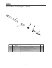
Fixed Pick Up Cylinder Assembly………………………………………………
41
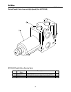
Pusher Motor Assembly………………………………………………………….
42
Carrier Hydraulic Assembly Hardware…………………………………………
43
Fixed Pick Up Arm Hydraulic Assembly Schematic……………………………..
44
RPU Hydraulic Assembly…………………………………………………………...
45
RPU Squeeze Cylinder…………………………………………………………..
46
RPU Lift Cylinder………………………………………………………………….
47
Pilot Check Valve Assembly………………………………………………….
48
RPU Rotate Cylinder……………………………………………………………..
49
Open-Center Configuration Schematic……………………………………………
50
Open-Center Valve………………….……………………………………………
51
1500 Bale Carrier Hydraulic Schematic…………………………………………..
53