


5
Electrical Installation & Diagrams
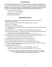
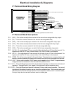
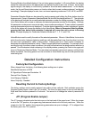
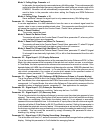
P1 Terminal Block Wiring Diagram
P1 Terminal Block Descriptions
P1-1 (2NC) This is the normally-closed contact of the second user assignable relay output.
P1-2 (2C) This is the common contact of the second user assignable relay.
P1-3 (2NO) This is the normally-open contact of the second user assignable relay output.
P1-4 (1NC) This is the normally-closed contact of the first user assignable relay output.
P1-5 (1C) This is the common contact of the first user assignable relay.
P1-6 (1NO) This is the normally-open contact of the first user assignable relay output.
P1-7 (AC / N) For single phase AC lines connect the Neutral side of your AC line to this terminal. For
systems with two hot AC lines, connect either of the Hot AC lines to this terminal.
P1-8 (AC / L) For single phase AC lines connect the Hot side of your AC line to this terminal. For
systems with two hot AC lines, connect either of the Hot AC lines to this terminal.
P1-9 (COM) This is the common point for the control logic. The speed sensor common lead as well
as any other source needing to reference the control common will be connected to this terminal.
P1-10 (+5V) This is a self-contained +5VDC power supply capable of up to 50mA. The speed sensor
supply lead can be connected to this terminal for its power source.
P1-11 (S1) This is the Signal input terminal for single channel operation or channel 1 of dual channel
operation. The signal lead of your speed or counter sensor will be connected here.
P1-12 (S2) This is the Signal input terminal for channel 2 during dual channel operation. The second
signal lead of the speed or position sensor should be connected here. This terminal is also used
as a reset input or function change input for various operations of the control. In counter modes,
this input may also be used as a counter reset or enable gate.
P1-1
P1-2
P1-3
P1-4
P1-5
P1-6
P1-7
P1-8
DTM8000-6
HOOK-UP
P1-9
P1-10
P1-11
P1-12
Alarm Output 2 - Normally Closed
Alarm Output 2 - Common
Alarm Output 2 - Normally Open
AC LINE INPUT
AC LINE INPUT
}
85-265VAC
}
Form C Relay Output (Programmable)
Alarm Output 1 - Normally Closed
Alarm Output 1 - Common
Alarm Output 1 - Normally Open
}
Form C
Relay Output
(Programmable)
AC NEUTRAL
AC LINE
2 Amp
PICK-UP
MOUNTED
black
white
red
COMMON
+5VDC
SIGNAL 1
SIGNAL 2
*
* Used for various functions, including quadrature counter mode.
NC2
C2
NO2
NC1
C1
NO1
N
L
COM
+5V
S1
S2