


12
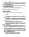
Parameter 25 Signal Input 1 (S1) Decimal Point (DP) Position
This selects the format of the display with respect to the decimal points position. This parameter
does not effect the value entry for other parameters. For example, it the user desires to display
10.00 at an input of 300RPM, then parameter 20 would be set to 1000, parameter 21 would be
set to 300, and parameter 25 would be set to 2.
Mode 0: Fixed XXXX
Mode 1: Fixed X.XXX
Mode 2: Fixed XX.XX
Mode 3: Fixed XXX.X
Mode 4: Fixed XXXX.
Parameter 26 Signal Input 1 (S1) Auto-Ranging Configuration
This selects how the unit auto-ranges and formats the numbers for the display.
Mode 0: Auto-Ranging Disabled
The auto-ranging mode is disabled. Ignoring decimal points, this limits the units display
range from 0 to 9999. Values beyond this range will display as an overflow error (-OF-).
Mode 1: Auto-Ranging On Overflow Only
In this mode, auto-ranging will only be activated if the display value exceeds the maximum
native display value. For example, in XX.XX decimal point mode, 99.99 would be the
maximum native value for a 4-digit display. When the display is in overflow, it will display
only the 4 most significant digits and the decimal point will flash.
Mode 2: Auto-Ranging Always Active
In this mode, auto-ranging is always active and continuously attempts to display the 4 most
significant digits. For example, the display will automatically range from 0.001 to 9999 as
needed. In this mode, any value over 9999 will be displayed as an overflow error (-OF-).
Parameter 27 Counter Reset / Preset Value
This is the value that will automatically be loaded into the display after the counter has been reset.
See Counter Reset Configuration, parameter 16, for more details.
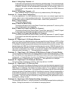
Parameter 30, 31, 32, 33, 34, 35, and 36
Reserved For Future Use.
Parameter 37 Signal Input 2 (S2) Counter Gate (Enable / Disable) Configuration
This selects how the S2 input is utilized in single channel counter modes.
Mode 1: Disabled (Required For Up / Down Counter Mode)
The S2 input will not function as a gate control and instead will act as the second input for
dual-channel counter operation.
Mode 2: Counting Enabled When S2 Input Low (Wired To Common)
The unit will continue to count input pulses as long as the S2 is in an electrically low state
or connected to the unit's common terminal. When the S2 input goes high (+5V) or is
allowed to float disconnected, the counter will be frozen at its current value.
Mode 3: Counting Enabled When S2 Input High (Not Wired To Common)
The unit will continue to count input pulses as long as the S2 is in an electrically high (+5V)
state or allowed to float disconnected. When the S2 input goes low or is wired to the unit's
common, the counter will be frozen at its current value.
Parameter 40 & 50 Alarm 1 & 2 Conditions
This defines which conditions will result in the alarm 1 or alarm 2 outputs being activated.
Mode 0: Always Inactive
The alarm output will remain in an inactive state. In this state, the NC and C contacts will
be internally electrically connected.
Mode 1: Always Active (When Power Is Applied)
The alarm output will become active when the power is applied to the unit. In this state,
the NO and C contacts will be internally electrically connected.
Mode 2: Active When Display Value Above Limit
The alarm output will activate when the displayed value is above the upper limit settings,
parameters 48 and 58 accordingly.