


18
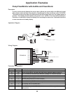
Bi-directional Incremental Position Display
Description:
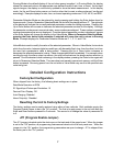
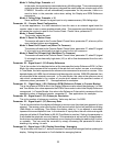
A system is needed which will track the position of a bi-directional linear-motion platform
and allow the user to select a home or zero position. The display should read in inches
and indicate the position of the platform at all times.
Application Diagram:
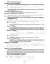
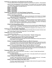
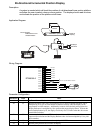
Wiring Diagram:
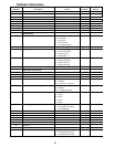
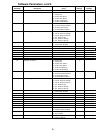
Parameter Configuration:
Parameter Value Notes
10 5 Up/Down Counter Mode
20 35 Because the initial values were 40 revolutions per 3.5 inches of platform motion, each is
multiplied by 10 to give an even number to increase accuracy since the display can be
programmed in whole numbers. Additionally, because of the decimal point position, the
Display Reference is multiplied by 10 to generate the proper display format. Without the
second multiplication by 10, the display would only read 3.5 inches when the drive motor
turned 400 revolutions.
21 400 In count mode, the Reference RPM is set in revolutions. 400 has been entered here to
represent 40 revolutions and the Display Reference has also been multiplied by 10 to yield
whole numbers.
22 10 Pulses per revolution of shaft encoder or pickup is 10 PPM
25 3 Decimal point position set to XXX.X on display
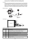
Coupling to
Chain Drive
Tach
Ite
m
ValuPage
TACHOMETER
ENTER
263.4
Drive Train Specs:
40 Revolutions = 3.5 In.
of Platform Motion
Encoder
Gear Motor
DTM8000 Meter
Motor Control
Connect to
Coupling
Linear-Motion System
Platform
P1-1
P1-2
P1-3
P1-4
P1-5
P1-6
P1-7
P1-8
DTM8000-6
P1-9
P1-10
P1-11
P1-12
Not Used
Not Used
Not Used
}
AC Line Input 85-265VAC, 50-60 Hz
2 Amp
Encoder
black
white
red
NC1
C1
NO1
N
L
COM
+5V
S1
S2
NC2
C2
NO2
Not Used
Not Used
Not Used
brown