


15
Application Examples
Pump Flow Monitor with Audible and Visual Alarm
Description:
A pump monitor which displays the pump rate in gallons per minute with an audible and visual
alarm output which will warn the operator of excessively low flow conditions under 5.00 GPM.
The alarm should not be able to be silenced and should be reset when any front-panel button is
pressed. The display should indicate in the format xx.xx (GPM). Due to normal fluctuations in
flow rates, it is desirable to have the display filter or average the value over 3 seconds to produce
a more accurate and steady display.
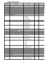
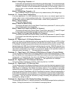
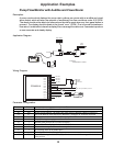
Application Diagram:
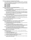
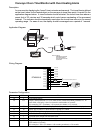
Wiring Diagram:
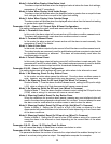
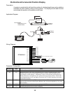
Parameter Configuration:
Tach
Ite
m
ValuPage
TACHOMETER
ENTER
36.24
Motor Control
Pump Specs:
53 Shaft Rotations = 3 Gallons
Encoder
Pump
Fluid
Outlet
Fluid
Inlet
Audible
Annunciator
DTM8000 Meter
P1-1
P1-2
P1-3
P1-4
P1-5
P1-6
P1-7
P1-8
DTM8000-6
P1-9
P1-10
P1-11
P1-12
Not Used
Not Used
Not Used
}
AC Line Input 85-265VAC, 50-60 Hz
2 Amp
Encoder
black
white
red
NC1
C1
NO1
N
L
COM
+5V
S1
S2
Not Used
NC2
C2
NO2
Not Used
120VAC
Audible
Annunciator
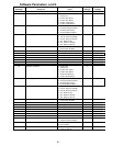
Parameter Value Notes
10 1 Rate Mode Setting (GPM is a rate-based unit)
20 300 Display should indicate 3.00 GPM (300) when motor at Reference RPM, parameter 21
21 53 This is the RPM at which the Display Reference, parameter 20, should be displayed
22 10 Pulses per revolution of shaft encoder or pickup is 10 PPR
24 3 Display filtering / averaging set to 3 seconds
25 2 Decimal point position set to XX.XX on display
40 3 Alarm active when display value is below lower limit
41 2 Constant alarm output with manual reset required
42 1 No silencing, reset on any button press
43 1 Flash display when alarm is active
47 500 Lower limit setting for 5.00 GPM (500). Limits are entered without regard for decimal
point position